23
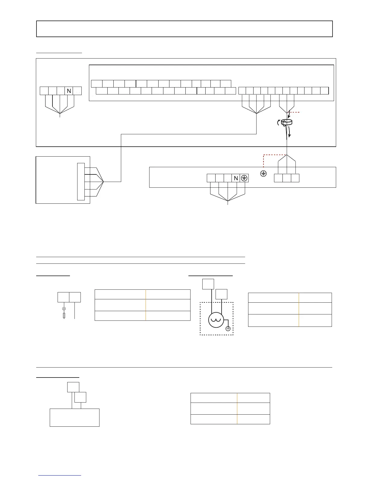
INSTALLATION
PE
Power Supply
L3L2L1
Power Supply
L3L2L1 EQP
Indoor Unit
Outdoor Unit
ABXYEPQ E T5 T5 T1b T1b
IBH1 IBH2 PE TH N C H A1 A2 N N N PE
IBH1 IBH2 TH PE TBH L1
AHS1 AHS2
P_o PE PE P_d SV2
3-shield wire
PE
COMANDO
REMOTO
ABXYE
Mod. 12T - 14T -16T
NOTA
Connect the communication cable between indoor unit and outdoor unit keeping the correspondence of the letters
indicated on the terminals (P with P, Q with Q, E with E).
Connect the communication cable between indoor unit and remote control keeping the correspondence of the let-
ters indicated on the terminals (A with A, B with B....).
OUTDOOR UNIT
REMOTE
CONTROL
Power supplie
Power supplie
comunication
(shielded cable)
INDOOR UNIT
☞
Connections between indoor unit terminal block and plant components
Remote alarm
Voltage
Passive signal port
(dry contact)
Maximum running
current
0.5A
Wiring size 0.75mm
2
2-way valve (SV2)
NOTE: The SV2 valve is powered when the heat pump is ope-
rating in HEAT mode.
Voltage 220-240VAC
Maximum running
current
0.2A
Wiring size 0.75mm
2
SV2
SV2
N
A1 A2
L
FUSE
N
DHW pump (P_d)
Voltage 220-240VAC
Maximum running
current
0.2A
Wiring size 0.75mm
2
DHW PUMP
CONTROL SIGNAL
OUTPUT
N
P_d
fi g. 2
fi g. 3 fi g. 4
fi g. 5
 Loading...