16
OPTIMAX HE PLUS 25 S
Cod. 3540R540 - 02/2009 (Rev. 00)
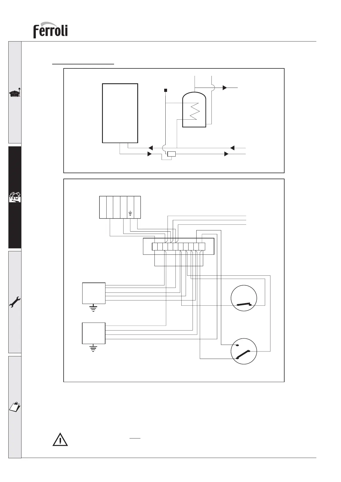
OPTIMAX “Y” Plan
fig. 16a
fig. 16b
OPTIMAX
FERROLI
BOILER
Auto air vent
Wiring diagram
4321
Junction Box
NL
12345678910
PROGRAMMER
NEUTRAL
LIVE
CH ON
DHW ON
DHW OFF
BLUE
WHITE
GREY
ORANGE
Room Thermostat
Cylinder Thermostat
N
E
L
240 Vac
Honeywell V4073H mid position
3 WAY ZONE VALVE
2
1
C
Terminal 5 - SWITCH LINE
L
6
5
Remove
Link
between
terminals 5-6
Pipe layout
2.6 Flue system
The unit is “type C” with a sealed chamber and forced draught, the air inlet and flue outlet must be
connected to one of the following flue systems. With the aid of the tables and methods of calculation indi-
cated, before commencing installation, it is first necessary to check that the flue system does not exceed
the maximum permissible length. The current standards and local regulations must be observed.
It should be noted that only Ferroli flue system and accessories should be used on this appliance,
as per BS 5440 2000 and C.E. test certification.
 Loading...