PEGASUS 23 T - 32 T - 35 T - 45 T
34
EN
cod. 3541E581 - Rev. 03 - 10/2019
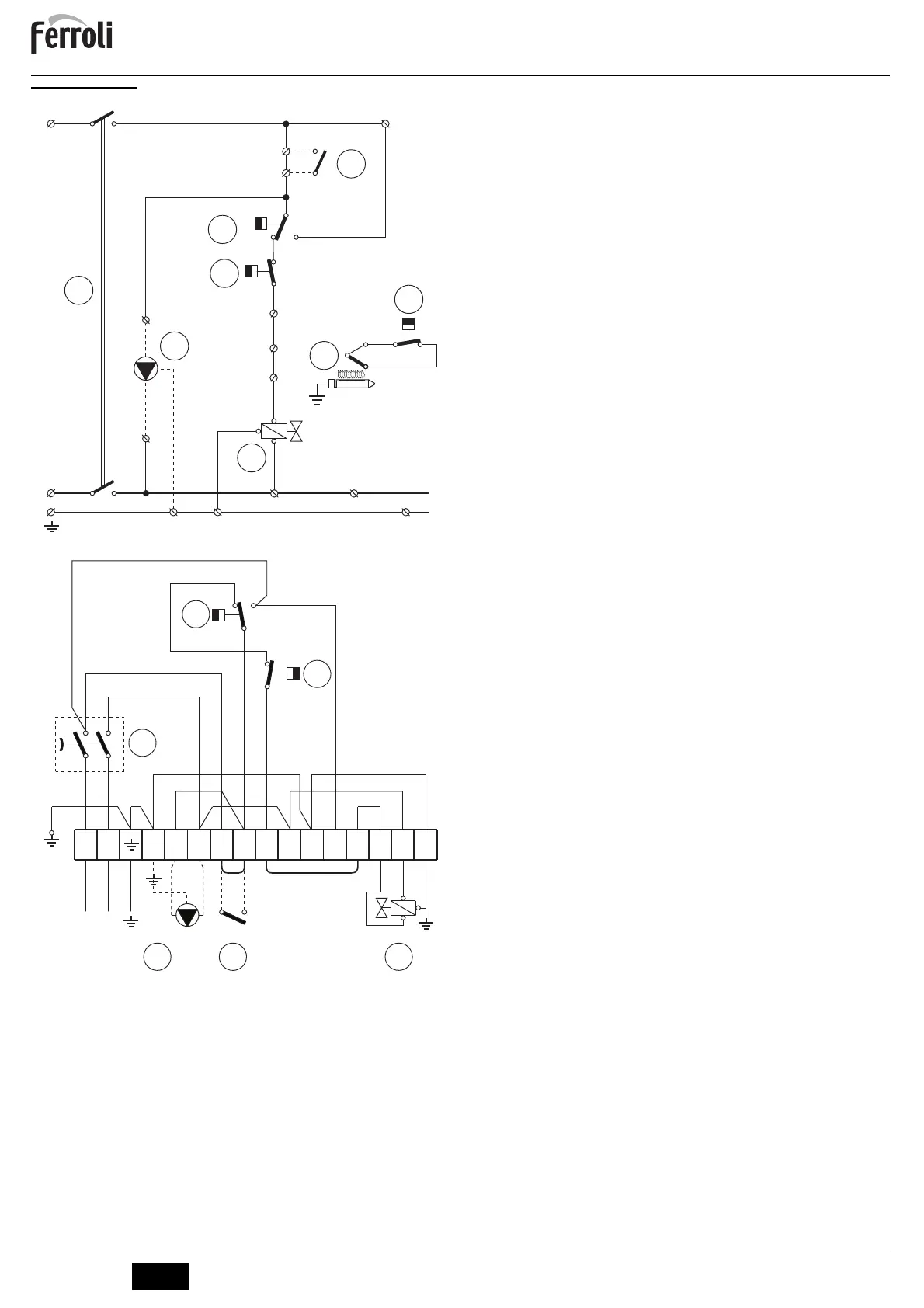
5.5 Wiring diagrams
fig. 16 - Main wiring diagram
fig. 17 - Connection wiring diagram
B
DISCONNECT THE JUMPER BETWEEN
TERMINALS 7 and 8 BEFORE CONNECT-
ING THE ROOM THERMOSTAT.
16 Fan
23 Thermocouple
32 Heating circulating pump (not supplied)
44 Gas valve
49 Safety thermostat
63 Boiler control thermostat
72 Room thermostat (not supplied)
98 Switch
126 Fume thermostat
L
12
230V
50Hz ~
N
34
5
6
4
16
15
10
11
9
13
14
C
2
1
2
C
7
8
12
44
98
63
126
32
72
49
C
2
23
L
N
C
1
1
2
3
4
L N 4 5 6 7 8 9 10 11 12 13 14 15
C
2
2
16
63
126
98
32 72 44
230V
50Hz
~
 Loading...