36
Tempra 12 - 18
0
5
1
2
3
4
6
98 63 145
8
14
81
9
32
56
20
44
7
82
49
34
5
87
27
22
19
29
16
31
50
43
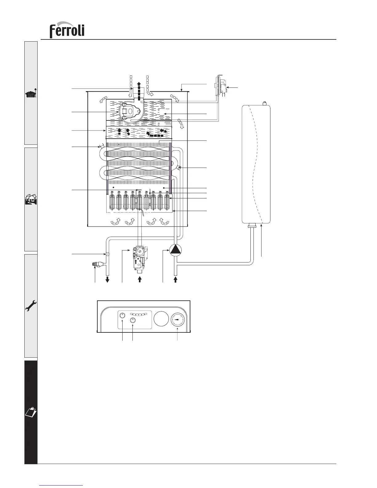
fig. 32
4.3 Hydraulic diagram
Key
5 - Room sealed compartment
7 - Gas supply
8 - Central Heating flow outlet
9 - Central Heating return inlet
14 - Safety valve
16 - Fan
19 - Combustion chamber
20 - Burner box
22 - Burner
27 - Copper heat exchanger
29 - Tube flue outlet
31 - Flue collector
32 - Pump
34 - C.H. flow temperature sensor
43 - Air pressure switch
44 - Gas valve
49 - Overheat cu-off thermostat
50 - Central heating limit thermostat
56 - Expansion vessel
63 - C.H. boiler thermostat
81 - Spark electrode
82 - Rectification electrode
87 - Gas pressure test point
98 - Main switch
145 - Pressure gauges





 To Next Page