8
Tempra 12 - 18
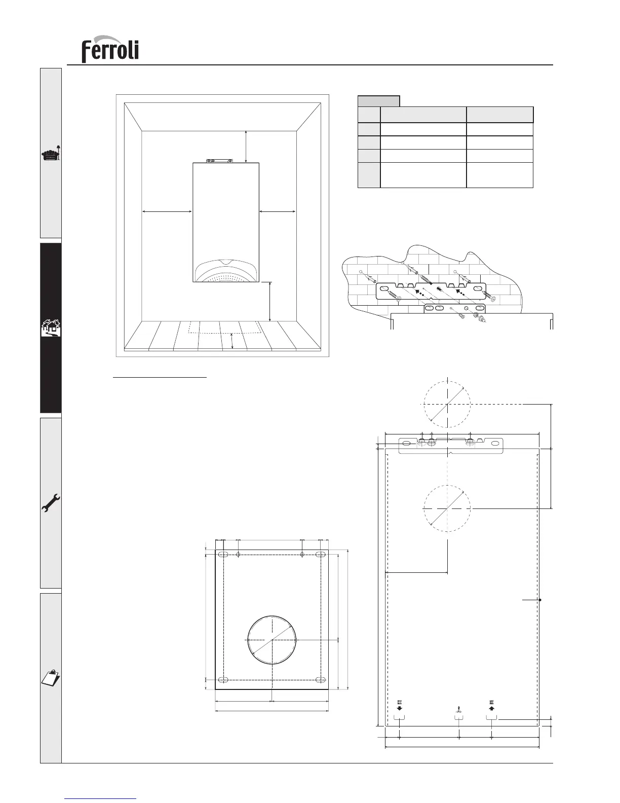
Fixing to the wall
For Top Flue connections.
Select suitable position for boiler, using the template mark
flue outlet and boiler mounting points. Drill two 10 mm holes
70 mm deep to accept the wall plugs. Fix the wall bracket to
the wall using standard lock nut (M8) on both sides. Mount the
boiler on the wall bracket and fix using the special antitheft
nut (M8) as described in the fig. 3a. Mount the boiler on the
wall bracket.
For Back Flue connections.
Select suitable position for boiler, using the plate inserted in
the optional “back flue outlet kit” mark flue hole and plate
fixing points.
Follow procedure in 2.6 for boiler transformation and mount-
ing.
fig. 3b
Boiler
dimensions
100 1802595
165 115
720 13
160
12485
400
36 155
16.5
120
120
A A
B
D
C
> 500 mm
Minimum Recommended
A
B
D
30 mm
150 mm
15 mm
(from opening panels)
150 mm
300 mm
C 150 mm 300 mm
Table 3
fig. 2
16.5
117.5 117.5
Øi 100
290
235
133 16.53831
102.5 177.5
20 260 10
fig. 4
fig. 3a