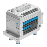
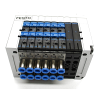
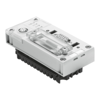
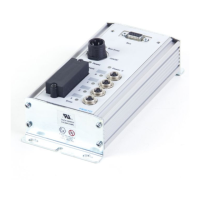
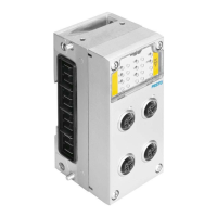
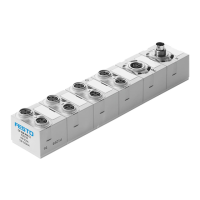
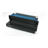
Do you have a question about the Festo CPV10-GE-DI02-8 and is the answer not in the manual?
Safety warnings regarding power supply, electrical isolation, and earth connection.
Details the pin assignment for the M12 power supply connection.
Details the pin assignment for the Sub-D-9 socket PROFIBUS-DP connection.
Step-by-step guide for configuring the CPV Direct, including DIL switches and extension connections.
Instructions for setting the PROFIBUS-DP station number using DIL switches 1-7.
Instructions for activating/deactivating device-related diagnosis using DIL switch 8.
General principles for addressing CPV valve terminals and modules in a CP extension string.
Explanation of LED indicators (PS, PL, BF, 4) for operating status and fault display.
Information on connecting CPI/CP modules and valve terminals to the CPI extension.
Procedure for saving string assignments using the SAVE button and associated LED.
| Product Type | Control Unit |
|---|---|
| Model | CPV10-GE-DI02-8 |
| Manufacturer | Festo |
| Number of Digital Inputs | 2 |
| Number of Outputs | 0 |
| Supply Voltage | 24 V DC |
| Nominal operating voltage DC | 24 V |
| Reverse polarity protection | Yes |
| Electrical isolation | Yes |
| Type of digital inputs | PNP |
| Cable length | 30 m |
| Short circuit strength | Yes |
| Overload protection | Yes |
| Protection class | IP65 |
| Mounting Type | DIN rail |
| Operating voltage range DC | 19.2 - 30 V |
| Input voltage range DC | 0 - 30 V |
| Storage temperature | -20 to 70 °C |

