

Do you have a question about the Festo CP-FB13-E and is the answer not in the manual?
Explains different danger warning types such as Warning, Caution, and Please note.
Provides essential safety precautions and general information before installation.
Details the procedure for setting dual inline switch elements on the field bus node.
Explains maximum field bus and branch line lengths based on baud rates.
Instructions for connecting CP modules to the bus system using special cables.
Guidelines for connecting the operating voltage, including safety precautions.
Information on connecting to the PROFIBUS DP interface using a sub-D plug.
Steps to prepare the CP system for PROFIBUS-DP operation, including voltage and assignments.
Details on configuring the CP system using Siemens masters like COM PROFIBUS and STEP 7.
Explains how to control the CP system using a general DP master, including bus start procedures.
Information on the device data base (GSD) required for configuring the CP system.
Explains the operating status indicated by LEDs on the CP node.
Describes the procedure for testing the valves connected to the CP terminal.
Details diagnostic possibilities supported by the CP system via PROFIBUS.
Explains how the CP system behaves and how to handle faults.
How to display device-specific diagnosis information using COM PROFIBUS 5.0.
How to perform online diagnosis using STEP 7, including diagnostic buffers.
Information on handling short circuits or overloads in output modules and sensor supplies.
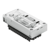
Lists general technical specifications for the CP FB13-E field bus node.
An alphabetical index of terms and topics covered in the manual.
| Operating Voltage | 24 V DC |
|---|---|
| Number of Digital Inputs | 8 |
| Number of Digital Outputs | 8 |
| Number of Outputs | 8 |
| Output Current | 0.5 A |
| Housing Material | Plastic |


