1. Installation
1-14
Festo Festo P .BE CP FB13-E-EN en 9910c
1.6 Connecting the PROFIBUS DP interface
Please note
Please note that only the Festo plug conforms with protection
class IP 65.
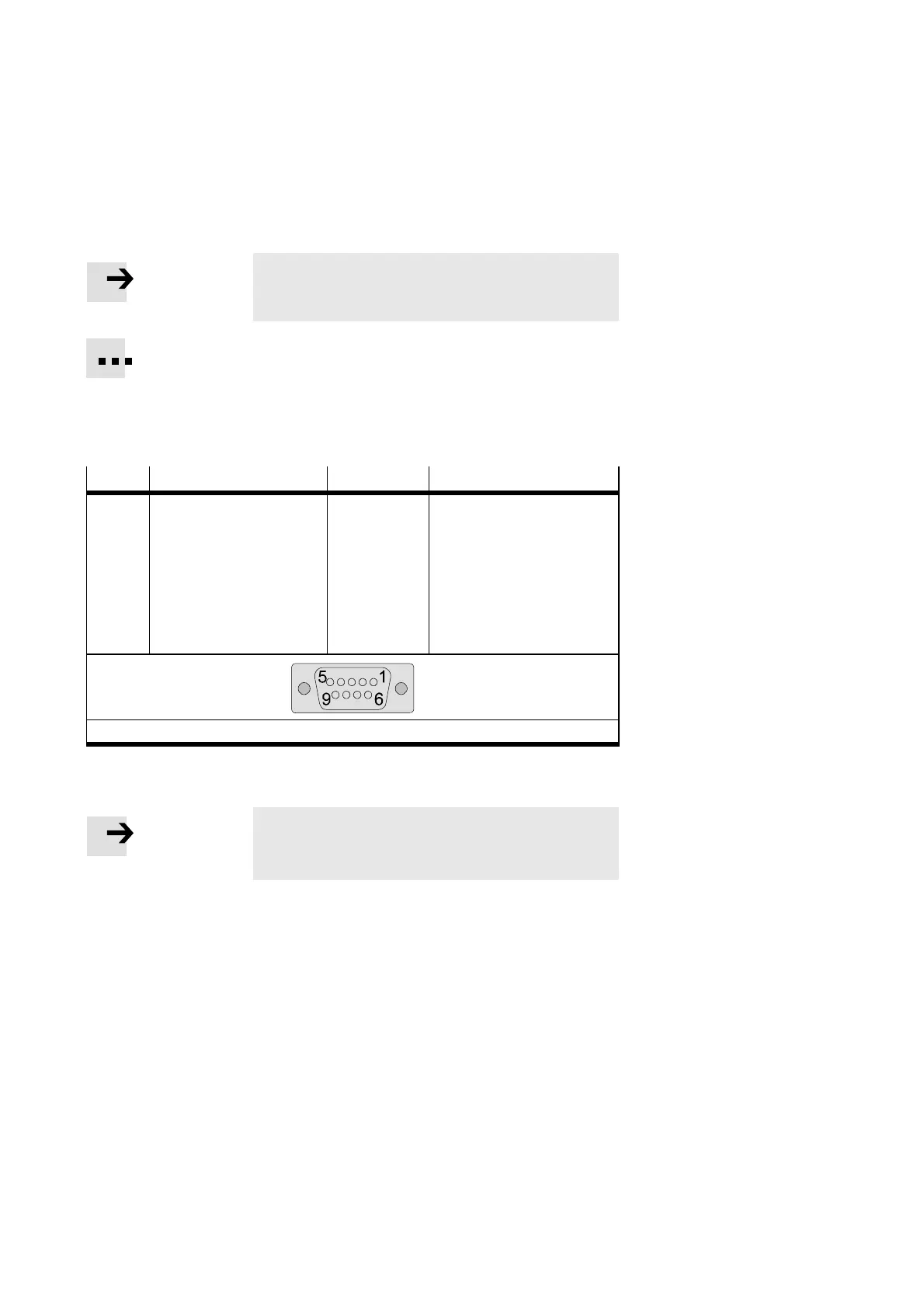
There is a sub-D connection on the node for connecting the
CPsystemtothePROFIBUS-DP.Thisconnectionisusedfor
the incoming cable, as well as for the continuing field bus
cable. Connect the node with the sub-D plug FBS-SUB-9-GS-9
(part no. 18529) from Festo. Outer diameter of the vcable for
the Festo sub-D plug: 6...9 mm.
Pin
Festo sub-D plug (IP65) PROFIBUS-DP Designation
1
2
3
4
5
6
7
8
9
Housing
B
A
Cable clip
n.c.
n.c.
RxD/TxD-P
CNTR-P
1)
DGND
VP
n.c.
RxD/TxD-N
n.c.
Screening/shield
not connected
not connected
Receive/send data-P
Repeater control signal
Data reference potential (M5V)
Power supply positive (P5V)not
connected
Receive/send data-N
not connected
Connection to housing
1)
Repeater control signal CNTR- P is designed as a TTL signal.
Fig. 1/5: Pin assignment of the field bus interface (looking down on socket)
Please note
Before connecting the sub-D plugs of other manufacturers:
replace the two flat screws by bolts (part no . 340960).