Do you have a question about the Festo Smart cubic CPV-SC Series and is the answer not in the manual?
Details danger categories, warnings, cautions, and notes for safe operation and handling of components.
Illustrates the various components that can make up the CPV-SC valve terminal, including end plates, blanking plates, valve sub-bases, and separator plates.
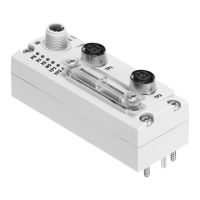
Identifies manual override, exhaust connections, and work/supply connections on the CPV-SC valve terminal.
Describes multipin connections, valve location labels, and yellow LEDs for signal status on the CPV-SC valve terminal.
Provides step-by-step instructions and dimensions for mounting the CPV-SC valve terminal onto a wall.
Details the requirements for compressed air quality, including oil content, for optimal valve terminal service life.
Guides the user through connecting auxiliary pilot air, managing pressure zones, and connecting supply and work lines.
Describes how to operate the CPV-SC valve terminal with multiple pressure zones using separator plates.
Illustrates external pilot air distribution and pressure zone separation, with notes on ensuring adequate pressure and exhaust.
Details how to connect pneumatic tubing for supply and work lines, including sealing unused connections and handling double-solenoid valves.
Provides safety warnings and notes on connecting electric cables, emphasizing power unit requirements and EMERGENCY STOP circuit checks.
Covers essential pre-commissioning steps, safety warnings for pressurization, and the importance of auxiliary pilot air for controlled start-up.
Outlines the process for commissioning, including preliminary pneumatic tubing tests and complete system setup.
Explains the operation of manual overrides for testing valve functions without electrical signals, including locking and non-locking types.
Details the procedure for testing the valve-cylinder combination using manual overrides, emphasizing safety and basic valve positions.
Provides a troubleshooting guide for pneumatic system impairments, detailing error treatments based on valve position and operating status.
Guides users through the process of safely removing and installing components within the valve terminal, including handling double-solenoid valves.
Details permitted temperature range, protection class, torques, materials, and fastening screw specifications.
| Mounting Position | Any |
|---|---|
| Nominal Operating Voltage DC | 24 V |
| Electrical Connection | M12 plug connector |
| Number of Valve Positions | 2, 3 |
| Valve Function | 5/2-way, 5/3-way |
| Operating Medium | Compressed air |
| Ambient Temperature | 0 to 50 °C |
| Protection Class | IP65 |
| Housing Material | Plastic |