Do you have a question about the Festo CPX-AP-A and is the answer not in the manual?
Lists documents relevant to the product and where to find them.
Identifies the specific product version this document refers to.
Explains product labelling and how to access further product information.
Lists the various standards that the product complies with.
Provides essential safety instructions for product usage and handling.
Defines intended uses and specifies requirements for qualified personnel.
Details UL/CSA certification information and conditions for USA and Canada.
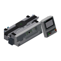
Explains the system architecture and components with a diagram.
Describes the modular design, including interlinking and electronics modules.
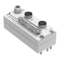
Details different product variants like interfaces and input/output modules.
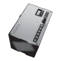
Describes basic, system supply, and forwarding interlinking modules.
Describes different types of end plates and their functions.
Explains LED indicators for status/diagnostics and module labelling elements.
Summarizes the overall function of the automation system and its adaptability.
Explains internal system communication and automatic module addressing.
Warns about problems caused by incorrect or non-approved connecting cables.
Explains system behavior during restart and configuration changes.
Lists available mounting types for the automation system modules.
Details procedures for H-rail and support system mounting.
Provides instructions for wall mounting and bracket placement.
Explains how to attach mounting brackets to modules.
Details device-side connections for interlinking modules with various connector types.
Provides safety guidelines and steps for connecting electrical cables.
Explains how the automation system receives its power supply, including connection examples.
Covers fuse protection for load supply and functional earthing procedures.
Provides guidelines to prevent malfunctions caused by electrostatic discharge.
Outlines steps to verify correct assembly and electrical connections.
Details interface configuration and system testing without an external controller.
Explains the process of commissioning the system within a network.
Explains the use of parameters to adapt the system to specific applications.
Lists diagnostic options and defines diagnostic statuses like Error and Warning.
Explains how diagnostic messages are grouped and presented.
Explains load voltage monitoring distinguishing under/overvoltage and shutdown conditions.
Provides safety precautions for handling electrostatically sensitive electronics modules.
Describes procedures for demounting and mounting interlinking and electronics modules.
Covers expansion procedures, including plausibility checks and address shifts.
Presents general technical specifications like temperature, humidity, and IP ratings.
Details mechanical specifications related to vibration and shock resistance.
Provides electrical specifications for power supply and capacitive load.
Outlines electrical data and ambient conditions specific to UL/CSA certification.
| Product Designation | CPX-AP-A |
|---|---|
| Reverse Polarity Protection | Yes |
| Max. Output Current per Channel | 0.5 A |
| Mounting Position | Any |
| Nominal Operating Voltage DC | 24 V DC |
| Electrical Isolation | Yes |
| Short Circuit Strength | Yes |
| Admissible Overall Current | 4 A |
| Number of Digital Inputs | 8 |
| Number of Digital Outputs | 8 |
| Digital Input Type | PNP |
| Digital Output Type | PNP |
| Nominal Output Voltage DC | 24 V DC |
| Total Output Current | 4 A |
| Switch-on Delay | Typically 1 ms |
| Switch-off Delay | Typically 1 ms |
| Storage Temperature | -25 °C to +85 °C |