Do you have a question about the Festo MS6 Series and is the answer not in the manual?
Identifies the intended audience and the document's focus on product use in safety systems.
Lists essential referenced documents and where to find all product documentation.
Specifies the standards and their versions relevant to the product's operation.
Outlines critical safety measures for handling, environment, and operation of the product.
Defines the product's proper application and lists potential hazardous misuses.
Emphasizes the need for qualified personnel to perform installation, operation, and maintenance.
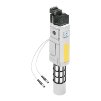
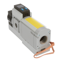
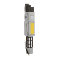
Illustrates the product's physical design, showing key elements and connections.
Lists selected product characteristics and their corresponding codes for understanding.
Explains the primary function of the soft start/quick exhaust valve in pneumatic systems.
Details the product's suitability for safety-related systems up to category 1, PL c.
Explains the safety functions of exhausting and preventing unexpected start-up.
Covers safe operation, ambient conditions, and usage time limits.
Lists critical safety metrics like B10, diagnostic coverage, and fault tolerance.
Essential preparation steps, including ensuring clean supply lines and proper placement.
Instructions for connecting the product with MS-series service unit components.
Guidelines for connecting pneumatic ports and electrical wiring, with safety warnings.
Steps for safely pressurizing the product and connected piping system.
Covers using tamper protection covers and resetting internal manual overrides.
Describes product behavior during voltage drops and after manual override actuation.
Instructions for routine maintenance, silencer checks, and cleaning the product.
Provides a guide for identifying and resolving common malfunctions.
Safety warning and steps for safely disconnecting all relevant connections before removal.
Comprehensive details on materials, environmental conditions, and certifications.
Graph illustrating how pressurization flow rate relates to the main flow control valve setting.
Explanation on setting the pressure switching point using the adjusting screw.
Table showing exhaust times under different volumes and operating pressures.
The Festo MS6(N)-SV-...-C is an electro-pneumatic soft start/quick exhaust valve designed for safe venting and pressure build-up in pneumatic piping systems and terminals within industrial environments. This device is intended for integration into machines or automation systems.
The primary function of the MS6(N)-SV-...-C is to control the pressurization and depressurization of pneumatic systems. It allows for a slow, controlled build-up of outlet pressure (p2) to prevent sudden, potentially damaging, pressure surges. This "soft start" capability is achieved through a main flow control valve, which regulates the filling time. Once the outlet pressure reaches a pre-set switching point, the valve fully opens, applying the complete operating pressure (p1) to the output port.
Conversely, the device also provides a "quick exhaust" function. In the event of a voltage drop, such as when the power supply is switched off, the product automatically exhausts the downstream piping system. This rapid depressurization is a critical safety feature, preventing unexpected movement or operation of pneumatic components.
The valve's safety functions include exhausting the downstream piping system and terminals, and preventing unexpected start-up (pressurization). These functions are activated by switching off the power supply at the pilot solenoid valve. When the voltage at the pilot solenoid valve is off, the connection between ports 2 and 3 is enabled, representing the safe state where the system can be safely vented.
The pressure switching point, which determines when the valve fully opens during pressurization, is adjustable via a dedicated screw. Similarly, the filling time during the soft start can be set using the main flow control valve.
The MS6(N)-SV-...-C is designed for straightforward integration and operation. It can be mounted in-line or with accessories such as module connectors, connecting plates, and mounting brackets. When installing, it is crucial to observe the flow direction from port 1 (compressed air input) to port 2 (pneumatic port outlet), indicated by numbers on the housing. The device should be placed to allow sufficient space for removing and installing the silencer, which is screwed into pneumatic port 3 (exhaust).
For safety-related systems, the setting and control elements must be protected by a cover (MS6-SV-C-MK) to prevent tampering. When this cover is mounted, the manual overrides cannot be actuated. In non-safety-related systems, the use of the cover is optional.
The product can be actuated through a manual override at the pilot solenoid valve or an internal manual override at the soft-start/quick exhaust valve. If the internal manual override is activated without the tamper protection cover, a reset is required. This reset can be performed either by outputting an electrical signal to the pilot solenoid valve or by actuating the manual override at the pilot solenoid valve. For specific variants like the MS6(N)-SV-...-C-10V24E, the internal manual override can only be reset through an electric signal to the pilot control solenoid valve, as it lacks a manual override.
The device is designed to operate with compressed air according to ISO 8573-1:2010 [7:4:4] and inert gases. Lubricated operation is possible, and if used, lubrication must be maintained.
Regular maintenance is essential to ensure the continued safe and proper functioning of the MS6(N)-SV-...-C. A key maintenance task involves checking the silencer. A dirty silencer can extend the time required for exhausting the system, thereby restricting the safety function. Therefore, the silencer should be checked regularly and replaced if necessary.
For cleaning, the product should first have its energy sources (operating voltage and compressed air) switched off. The exterior of the product can then be cleaned with soap suds (max. +50 °C), petroleum ether, and other non-abrasive cleaning agents.
In the event of malfunctions or failures, repairs to the product are not permissible. The product should be replaced, and Festo should be informed about the failure. Defective products should be returned to Festo.
To ensure the safety function works properly, the product must be actuated at least once per month. This helps to prevent potential issues that could arise from prolonged inactivity.
Before any installation or maintenance work, it is critical to switch off the compressed air supply and secure it against being switched on again to prevent the risk of injury from compressed air. Similarly, for electrical connections, especially with extra-low voltages, only PELV circuits that guarantee reinforced isolation from the mains network should be used, observing relevant IEC standards. For higher voltages, electrical connections must only be established when the voltage is disconnected and by qualified personnel.
| Port Size | G1/8, G1/4 |
|---|---|
| Medium | Compressed air |
| Medium Temperature | -10°C to +60°C |
| Ambient Temperature | -10°C to +60°C |
| Protection Class | IP65 |