Do you have a question about the Festo MS6-SV and is the answer not in the manual?
Describes the two operational modes: Automatic and Monitored start.
Details requirements for specialist installation and commissioning by trained personnel.
Guidelines for placing the device, minimum distances, and orientation.
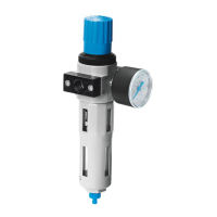
Instructions for combining the MS6(N)-SV with other MS series units.
Details for connecting pneumatic ports 1 and 2, including thread sizes and screw-in depth.
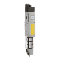
Recommendations for connecting pneumatic port 3, emphasizing silencer use due to noise.
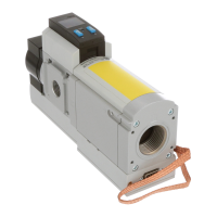
Steps for properly connecting the earth cable for safety and EMC.
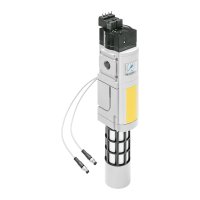
Instructions for connecting the approved NECA multi-pin plug sockets.
Example wiring for the MS6(N)-SV with a specific multi-pin plug socket.
Example wiring for the MS6(N)-SV with another multi-pin plug socket.
Explains the two operating modes and their control signals.
Details on using signal contacts for feedback in safety control systems.
Step-by-step guide for device startup and explanation of input/output behavior.
Explains the meaning of Power LED and Error LED states for status.
Lists fault codes and their corresponding causes and troubleshooting steps.
Details safety-related standards, performance levels, and integrity levels.
Provides key operational parameters like connections, medium, pressure, and flow.
| Size | 6 |
|---|---|
| Series | MS |
| Mounting position | Any |
| Ambient temperature | -10 ... 60 °C |
| Housing material | Die-cast aluminum |
| Seals material | NBR |
| Operating pressure | 2 ... 10 bar |
| Weight | 1, 100 g |