Do you have a question about the Festo DSNU-S and is the answer not in the manual?
Lists all available documents for the product.
General safety instructions, intended use, and personnel qualifications.
Links to accessories, spare parts, and contact for technical support.
Explains the basic function and movement of the cylinder.
Details the main components and design elements of the cylinder.
Key points for proper installation, including alignment and torque.
Measures to avoid misalignment and ensure proper coupling for longevity.
Use of shock absorbers/external stops for specific operating conditions.
Preventing payload sliding and using flow control valves for speed.
Instructions for connecting hoses to the cylinder's supply ports.
Steps for gradual start-up, pressurization, and initial testing.
Warning regarding collision risk due to projecting payloads during adjustment.
Guidelines for cleaning the product and maintaining its service life.
Troubleshooting common malfunctions and their causes/remedies.
Specifications including size, connections, pressure, temperature, and forces.
Specifications for larger cylinder sizes.
Specifications for the DSNU-S variant.
Guidelines for environmentally friendly recycling of the product and packaging.
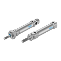
This document describes the DSNU(-S) round cylinder, an industrial pneumatic actuator designed for the transport of loads. It provides comprehensive instructions for its operation, installation, maintenance, and troubleshooting.
The DSNU(-S) round cylinder operates on pneumatic principles. When the cylinder chamber is pressurized, the piston rod extends outwards. Retraction of the piston rod depends on the cylinder type: for single-acting cylinders, an integrated return spring facilitates retraction, while for double-acting cylinders, pressurizing the other cylinder chamber causes retraction. The cylinder force during advance and return can vary; it is different when the piston rod is at one end and identical with a through piston rod. The position of the piston can be detected by proximity sensors, allowing for precise control and monitoring within automated systems.
The DSNU(-S) cylinder is designed for versatile application in various industrial settings. It is crucial to consider the ambient conditions at the location of use to ensure optimal performance and longevity. The product should only be used in its original status, without any unauthorized modifications, to maintain its integrity and safety. All labeling on the product must be observed.
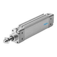
For mounting the payload, the piston rod features a male thread. The bearing cap and end cap also have male threads for mounting purposes, and a cross hole is provided for additional mounting flexibility. For DSNU-S models, the end cap mounting thread is available for sizes 20 and 25 only.
During installation, the cylinder must be handled carefully to avoid damage to the cylinder barrel and piston rod. Key installation points include ensuring parallel installation when using external guides and avoiding distortion. Compliance with permissible loads is essential, and tightening torques for lock nuts on the male thread must be strictly observed to prevent damage and ensure secure operation.
To prevent mechanical alignment inaccuracies between the piston rod and an external guide, several measures can be employed: ensuring absolutely precise alignment, using a self-aligning rod coupler (FK), or utilizing a guide unit (FEN) with a compensating coupling. A rigid coupling can impair the cylinder's service life and function, so flexible solutions are often preferred. For applications involving large payloads, high piston speeds, or quick exhaust valves, suitable shock absorbers or external stops should be used to manage forces and prevent damage.
To prevent the payload from sliding down suddenly in the event of an air supply failure in horizontal or sloping mounting positions, piloted check valves should be used. Speed adjustment is achieved using one-way flow control valves. For single-acting cylinders, the GRLZ valve is used for supply air, while for double-acting cylinders, the GRLA valve is used for exhaust air. These valves are screwed directly into the supply ports. Using other accessories with an excessive screw-in depth can damage the cushioning piston.
For position sensing, proximity sensors with a mounting kit are recommended. It is important to avoid external influences from magnetic or ferritic parts near the proximity sensors, maintaining a spacing of at least 10 mm.
Pneumatic installation involves connecting hoses to the supply ports. Commissioning requires slowly pressurizing the system, often using a soft start valve for gradual start-up. For medium or large payloads or high speeds, sufficiently large arrester fixtures should be used, as the product can tolerate maximum velocities and payloads without external arrester fixtures.
During processing, it is critical to only turn adjusting screws while the product is stationary to avoid collision risks with payloads. The speed adjustment procedure involves closing one-way flow control valves on both sides, then unscrewing them one complete turn. The cylinder is then simultaneously pressurized at both ends, allowing the piston rod to move slightly to a point of balance. Exhausting the cylinder at one end moves the piston rod to an end position. After starting a test run, if the piston rod strikes hard against the end positions or rebounds, the speed should be corrected using the one-way flow control valve.
The DSNU(-S) cylinder is designed for minimal maintenance. It is important to store the product in a cool, dry, UV-protected, and corrosion-protected environment, ensuring that storage times are kept to a minimum. Before any mounting, installation, or maintenance work, the compressed air supply must be switched off and secured to prevent accidental re-engagement. Tightening torques must be observed, with a general tolerance of ± 20% unless otherwise specified.
Cleaning the product should be done with a soft cloth. Aggressive cleaning agents must not be used. The guide elements should not be cleaned, and lubricant should be regularly removed from the piston rod surface to prevent reduced service life. The cylinder is largely maintenance-free due to lifetime lubrication.
Troubleshooting guidance is provided for common malfunctions. For instance, if false triggering occurs during position sensing, it may be due to temperatures being too high or too low, requiring compliance with the permissible temperature range of the proximity sensors. If the fault is at the proximity sensor itself, referring to its instruction manual is advised.
Irregular movement of the piston rod (cylinder jolts) can be caused by a lack of lubricant, which can be remedied by applying lubricant according to the wearing parts sheet. If one-way flow control valves restrict the flow of supply air, controlling the exhaust air flow (not the supply air) might help. A dirty piston rod can be cleaned, and covering should be provided, with relubrication after thorough cleaning. Insufficient supply air (stick slip) can be addressed by keeping tubing lines short, selecting suitable cross-sections, choosing the correct pressure, and maintaining constant pressure. If the pressure is too low, connecting volume upstream is recommended. If the guide is not parallel to the direction of stroke, using a self-aligning rod coupler from the accessories catalogue is advised.
If the piston does not travel to the end position, potential causes include a damaged cylinder barrel (requiring replacement), a completely closed setting screw for end-position cushioning (requiring loosening), foreign matter in the cylinder (requiring filtering of compressed air), or the cylinder traveling to an external end stop (requiring readjustment of the end stop).
At the end of its useful life, the product and packaging should be disposed of through environmentally friendly recycling in accordance with applicable regulations.
| Mounting type | Various options including foot, flange, and clevis |
|---|---|
| Ambient temperature | -20 °C to +80 °C |
| Materials | Aluminum, stainless steel, and other materials |
| Operating medium | Compressed air |
| Material | Aluminum, stainless steel, and other materials |