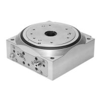
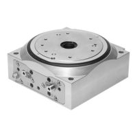
The Festo DHTG is a double-acting rotary indexing table that operates on the toothed rack and pinion principle, designed for precise angular positioning of workloads. This robust rotary drive incorporates forced locking, with larger sizes (from DHTG-140) also featuring overload protection. Its fundamental operation involves two toothed rod pistons that move back and forth when compressed air ports are alternately pressurized. This linear motion is then converted into a rotary movement via a pinion. A second pair of pistons is dedicated to controlling the engagement of the pinion in the table gearing and securing the holding position. Integrated shock absorbers ensure smooth braking of the rotary indexing table in the direction of rotation. The DHTG is specifically engineered to turn a workload by a defined angle into a stable holding position.
For optimal performance and longevity, several usage features and requirements must be observed. When handling the DHTG, it is crucial to consider its weight, which can be up to 25 kg. Proper storage conditions are essential, requiring short storage times in a cool, dry, shaded, and corrosion-resistant environment. Before use, all transport packaging, such as foils, caps, and cartons (excluding sealing elements in pneumatic connections and proximity switch holes), must be removed. The packaging is designed for recycling, with the exception of oiled paper, which should be disposed of as other waste. The product should be used in its original condition without any unauthorized modifications. When tightening components, a tolerance of ±20% should be applied to the specified torques, unless otherwise stated.
Improper handling can lead to malfunctions, so it is imperative to always comply with the specifications outlined in the manual. Users must compare the maximum values provided in the operating instructions (e.g., forces, torques, temperatures, masses, speeds) with those of their actual application. Adhering to these load limits is critical for safe operation and compliance with relevant safety regulations. Ambient conditions at the location of use should also be considered, as corrosive environments can reduce the service life of the DHTG. A supply of correctly prepared compressed air is necessary, and the selected medium must be maintained throughout the product's service life. For instance, only non-lubricated compressed air should be used. The entire system should be pressurized slowly to prevent uncontrolled movements, and a safety start-up valve, such as type HEL, is recommended for slow start-up pressurization. Compliance with regulations from trade associations, the German Technical Control Board, or relevant national regulations is also mandatory.
Mechanical assembly involves ensuring sufficient space for pneumatic connections, conversion, or shock absorber replacement. The DHTG is fastened using four screws and ZBH centring sleeves, with specific tightening torques provided for direct mounting from above and below, depending on the size. Blank plate mounting requires 6 screws and 2 centring pins, with cover caps provided to seal the screw recesses after fitting.
For pneumatic system installation, the pneumatic ports A to D must be connected, removing any sealing elements if present. The manual details connections for clockwise or anti-clockwise rotation and reciprocating operation, specifying connecting threads and tightening torques. For reciprocating operation, a separate kit and an external flow control valve may be required. The manual provides examples of simple and extended interfaces for both clockwise/anti-clockwise rotation and reciprocating operation/flexible control, illustrating the necessary valve configurations. It is important to note that if the product is used in safety-relevant applications, additional measures, such as observing EU machine guidelines, are necessary. Without these measures, the product is not suitable for safety-related sections of control systems.
Electrical installation involves position sensing using proximity switches. Faulty switching or damage can occur if proximity switches are screwed in too far. Therefore, users must ensure that these switches are screwed into the threads (U), (V), or (W) only up to the specified maximum depth. The manual provides a table detailing the maximum screw-in depths for different sizes and threads. It also specifies the direction of rotation for plate sensing, linking clockwise rotation to (W) for direction, (V) for locking, and (U) for piston end position, and anti-clockwise rotation to (U), (V), and (W) respectively. For DHTG-140 and DHTG-220 models with a 3-part split, the rotating plate can engage in an intermediate position corresponding to 6-index stations. After an emergency stop or overload, it is crucial to ensure the rotating plate is in the desired position before resuming operation. If it is engaged in an intermediate position, it must be brought to the desired position by jerking and twisting against the overload protection.
Commissioning requires careful attention to safety. A warning highlights the risk of injury from rotating masses, emphasizing the need to ensure no one places their hand in the DHTG's positioning range and that no objects obstruct its path, recommending a protective screen. Incorrect functioning can result from inaccurate toothed rod position; if the DHTG is exhausted, the resetting force of the shock absorber can push the rotary table out of the end position into an undefined state. Before each commissioning, the last pressurized connection must be pressurized: connection (B) for clockwise/anti-clockwise rotation, or connection (C) or (D) for reciprocating operation/flexible control. Clockwise rotation is internally controlled via the flow control valve, while reciprocating operation requires external control through an additional one-way flow control valve (GRLA). The flow control screw should be screwed in completely, then loosened one rotation. The complete system should be slowly pressurized with at least 4 bar. A test run should then be performed, and modifications such as readjusting proximity switches, increasing speed by unscrewing the flow-control screw, and setting the cushioning may be necessary. The manual provides detailed steps for clockwise/anti-clockwise rotation and reciprocating operation, including examples for different rotation sequences. It is important to note the maximum permitted frequencies as a factor of the moment of mass inertia and to ensure the rotary indexing table does not strike hard against end stops or trigger overload protection. The test run should be ended once these checks are complete.
Setting the cushioning involves loosening the clamping element (K) one rotation and screwing in the adjusting screw (6) until the desired cushioning is achieved. The rotary indexing table must not strike hard against the end stops, and the overload protection must not be triggered. The maximum moment of mass inertia must not be exceeded. Screwing in the adjusting screw increases cushioning, while unscrewing it reduces cushioning. After adjustment, the clamping element (K) must be tightened again, with specific tightening torques provided for different sizes.
During operation, a warning reiterates the risk of injury from rotating masses, stressing the importance of keeping hands and objects clear of the DHTG's positioning range. The moment of mass inertia as a factor of switching or cycle frequency should be noted, referring to characteristic curves. The maximum achievable switching frequency, as a factor of the moment of mass inertia, can be found in the "Switching frequency" diagram. The switching time can be calculated as T = 60/f, where f is the frequency. The response time includes unlocking, turning, locking, and the return stroke of the work piston. The actual cycle time is calculated as switching time + processing time + dwell time. Processing time depends on the customer application, and dwell time may be necessary if the actual cycle time is less than the minimum possible cycle time. It is important to note that the viscosity of shock absorber oil decreases with increasing heat, potentially causing the shock absorber to strike through if the device operates for too long. In such cases, the moment of mass inertia should be reduced. Contact with aggressive media, grinding dust, or glowing sparks/chips must be avoided, as these can damage the DHTG.
Maintenance and care involve switching off power supplies (operating voltage and compressed air) before any work. The DHTG should only be cleaned with a soft cloth, and all non-abrasive cleaning agents are permitted. Due to its service life lubrication, the DHTG typically does not require additional maintenance. However, regular removal of lubricating grease from the piston rod surface will reduce its service life. After a conversion, such as to reciprocating operation, specific components (piston, piston chamber, seal, lock, toothed rod, pinion, table bearing, dividing disc) should be lubricated with LUB-E1. It is recommended to relubricate mechanical components every 5 million switching cycles. Shock absorbers should be checked every 2 million strokes for oil leakage, hard knocking, and proper function (the shock absorber head must not remain in the retracted end position).
For dismantling and repairs, it is recommended to return the product to Festo's repair service for overhaul, as they can perform necessary fine adjustments and tests. Information on spare parts and aids can be found on www.festo.com/spareparts. Before any dismantling, power supplies must be switched off, and the system and product must be exhausted. Replacing the integrated shock absorber involves unscrewing the flow-control screw, fastening screws on the sub-base, removing the retaining ring with pliers, replacing the shock absorber, and then reassembling in reverse sequence with specified tightening torques. Conversion from clockwise to anti-clockwise rotation involves a detailed sequence of loosening clamping elements, unscrewing adjusting screws, flow control screws, and fastening screws, removing retaining rings, repositioning the shock absorber, O-ring, and distance piece, and then reassembling with specific tightening torques. The open holes (R) or (L) determine the direction of rotation. After conversion, the adjusting screw must be screwed in until the desired cushioning is achieved, and the clamping element tightened.
Troubleshooting guidance is provided for various malfunctions. If the rotating plate does not move, possible causes include active overload protection (remedy: pressurize connection (B) and turn the plate back against the direction of rotation until the overload protection and locking mechanism engage audibly) or audible leakage/closed flow-control screw (remedy: send DHTG to Festo or open screw). If the rotating plate does not engage, the end position may not be reached (remedy: unscrew the adjusting screw for the shock absorber until the plate engages), or overload protection may be active (remedy: see above). If the toothed disc and pinion stand tooth on tooth, contact Festo's Technical Hotline. Hard metal impact at the end position could be due to an unscrewed adjusting screw for the shock absorber (remedy: screw in the adjusting screw) or a defective shock absorber (remedy: replace it). Hard metallic knocking in the locking mechanism indicates the adjusting screw for the shock absorber is screwed in too far (remedy: unscrew the adjusting screw). Incorrect plate position (overload protection engaged incorrectly at 180°) requires forcing the overload protection and turning until it re-engages.