DHTG
Festo – DHTG – 2018-02e English 15
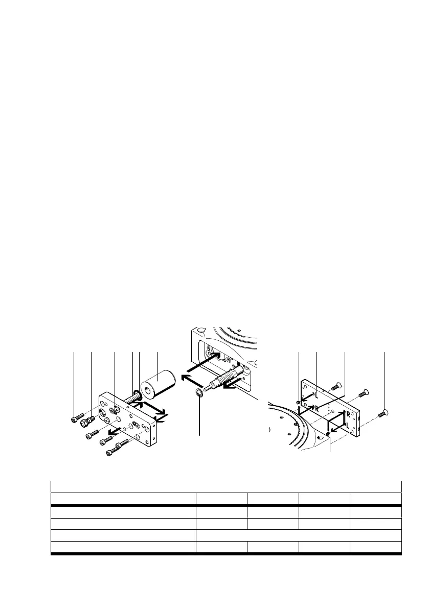
Conversion from clockwise rotation (as supplied) to anti-clockwise rotation:
1. Loosen the clamping element (K) of the adjusting screw one rotation.
2. Unscrew the adjusting screw 6 a few rotations.
3. Unscrew flow control screw aJ and the fastening screws (M) from the sub-base.
4. Using pliers, remove the retaining ring (S) on the shock absorber.
5. Fit the following:
– the shock absorber with the retaining ring in the adjacent hole
– the O-ring (P) / buffer (for DHTG-65) in the adjacent groove
– the distance piece (T) in the same hole (distance piece omitted for 2/3 index stations)
– the sub-base with the fastening screws and the flow control screw in reverse sequence
(tightening torque è Tab. 17).
6. Unscrew the fastening screws (N) on the stop plate.
7. Unscrew:
– both locking screws (O) on the rear of the stop plate to begin with,
– then screw them in again into the open holes (tightening torque è Tab. 17).
The open holes (R) or (L) in Fig. 14 determine the direction of rotation
(Holes (R) open: clockwise rotation).
8. Screw the fastening screws (N) on the stop plate again (tightening torque è Tab. 17).
The rotary indexing table remains pneumatically controlled as before.
9. Screw in the adjusting screw 6 until the desired cushioning is achieved è Fig. 11.
10.Tighten the clamping element (K) of the adjusting screw (tightening torque è Tab. 15).
(M) aJ (N)(O)(P)(K) (L) (R)(T)
(S)
6
Fig. 14
Tightening torque
Size 65 90 140 220
Flow control screw aJ [Nm] 1.5 1.5 5.5 5.5
Fastening screws (M) [Nm] 2.9 2.9 9.9 9.9
Plug screw (O) [Nm] 0.5
Fastening screws (N) [Nm] 1.5 2.9 5.9 5.9
Tab. 17