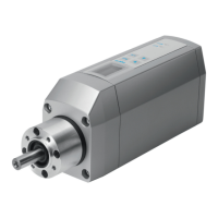
EMCA-EC-67-...-EC/-EP/-PN
Festo SE & Co. KG
Ruiter Straße 82
73734 Esslingen
Germany
+49 711 347-0
www.festo.com
Brief description
Translation of the original instructions
8074569
1710a
[8074562]
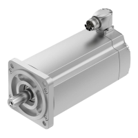
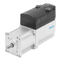
Integrated drive EMCA-EC-67-...-EC/-PN/-EP English.......................
EtherCAT
®
, EtherNet/IP
®
and PI PROFIBUS PROFINET
®
are registered trademarks
of the respective trademark owners in certain countries.
All available documents for the product è www.festo.com/pk.
This brief description is intended solely for initial information. The user document
ation for the product also includes the following documents:
User documentation for the product
Manual
EMCA-EC-SY-...
Device and functional description;
Mounting, installation, commissioning and diagnostics
Manual
EMCA-EC-S1-...
Description of the safety function “Safely switched-off torque” (Safe
torque off/STO)
Manual
EMCA-EC-C-HP-...
Description of the device profile FHPP (Festo Handling and Position
ing Profile)
Help for the EMCA FCT
plug-in
Online help of the Festo Configuration Tool (FCT) for commissioning
and parameterisation
Special documentation
EMCA-EC_UL-...
Requirements for operating the product in the USA and Canada in
accordance with certification by Underwriters Laboratories Inc. (UL)
1 Safety
Always observe the safety information and warnings in the documentation of
the product and of the other components used.
Before mounting and installation work, switch off supply voltage and secure it
against being switched on again. Only switch on the supply voltage again when
mounting and installation work is complete.
Never remove or insert a plug connector when the motor controller is powered.
Observe the handling specifications for electrostatically sensitive devices.
Only enable the controller if the drive has been professionally installed and fully
parameterised.
Do not carry out repairs on the device. If defective, replace the device.
Besides the 4 screws on the housing cover, do not loosen any additional screws.
Warning
Danger of burns from hot housing surfaces.
Contact with the motor housing can cause burn injuries. This can frighten people
and cause them to act in an unpredictable manner. This can lead to other forms
of secondary damage.
Make sure that unintentional contact is not possible.
Inform operating and maintenance staff about the possible hazards.
Let the drive cool down to room temperature before maintenance work.
Warning
Rapidly rotating motor shaft with high torque.
Clothing, jewellery and hair can be caught and wrapped around the shaft. People
can be injured as a result.
Make sure that clothing, jewellery or hair cannot be caught by the rotating
motor shaft.
Ensure that clothing fits tightly.
Personnel with long hair must wear hair nets.
Caution
Rapidly rotating motor shaft with high torque.
Contact with the motor shaft can cause burn injuries and abrasions.
Ensure that the rotating motor shaft and components attached to it cannot be
touched.
Note
Gas formation with fire risk.
If cleaning agents make contact with the hot surface of the motor, gases can
form and ignite.
Prior to cleaning work, let the drive cool down to room temperature.
Pay attention to the instructions for use of the cleaning agent.
1.1 Use for intended purpose
The product is intended for driving and controlling electromechanical drives. The
product is intended for installation in a machine.
Use exclusively:
– in perfect technical condition
– in original status without unauthorised modifications; only the expansions de
scribed in the documentation supplied with the product are permitted
– within the limits of the product defined through the technical data
– in an industrial environment
The product is intended for use in industrial environments. Outside of industrial
environments, measures may need to be implemented for radio interference sup
pression, e.g. in commercial and mixed-residential areas.
1.2 Intended use of the STO function
The STO function (safe torque off ) in accordance with EN61800-5-2 is intended to
shut down the torque of the integrated motor. The STO function prevents unexpec
ted start-up of the integrated motor. The STO function may only be used in applica
tions in which the specified safety characteristics suffice.
Safety characteristics
The product’s STO function fulfils requirements for the following characteristic
safety values:
– PLd/cat.3 in accordance with ISO13849-1 (Performance Level/PL)
– SIL 2 in accordance with EN61800-5-2 (Safety Integrity Level/SIL)
– SILCL2 in accordance with IEC62061 (Claim Limit/CL)
The achievable safety level depends on the other components used to implement a
safety function.
To protect against unintended motor start-up, the controller of the product must
be activated via the connection [X6] with the category required for the application
in accordance with ISO 13849-1, e.g. via an external safety relay.
Qualification of the specialist staff (requirements for staff)
The product may be placed in operation only by a qualified electro technician, who
is familiar with the topics:
– installation and operation of electrical control systems
– applicable regulations for operating safety-engineering systems
– applicable regulations for accident prevention and occupational safety
– documentation for the product
Diagnostic coverage (DC) for the safety function
Diagnostic coverage is determined by inclusion of the product in the control chain
and the measures implemented for the diagnostics. In order to achieve the spe
cified diagnostic coverage, the status of the acknowledgment contact must be
evaluated by the control system every time the STO function is requested. If a
potentially dangerous malfunction is recognised during the diagnostics, appropri
ate measures must be taken to maintain the safety level.
Note
The device cannot detect a cross circuit in the input circuit by itself.
If required, use a safety switching device with cross circuit detection.
1.3 Foreseeable misuse of the STO function
The following foreseeable misuses are among those not approved as intended use:
– Bridging of the STO function
– Applications where switching off can result in hazardous movements or condi
tions
Note
The STO function is not sufficient as the sole safety function for drives that are
subject to permanent torque or force (e.g. suspended loads, vertical axes).