3 Installation
3-21
Festo FED-… en 1107g
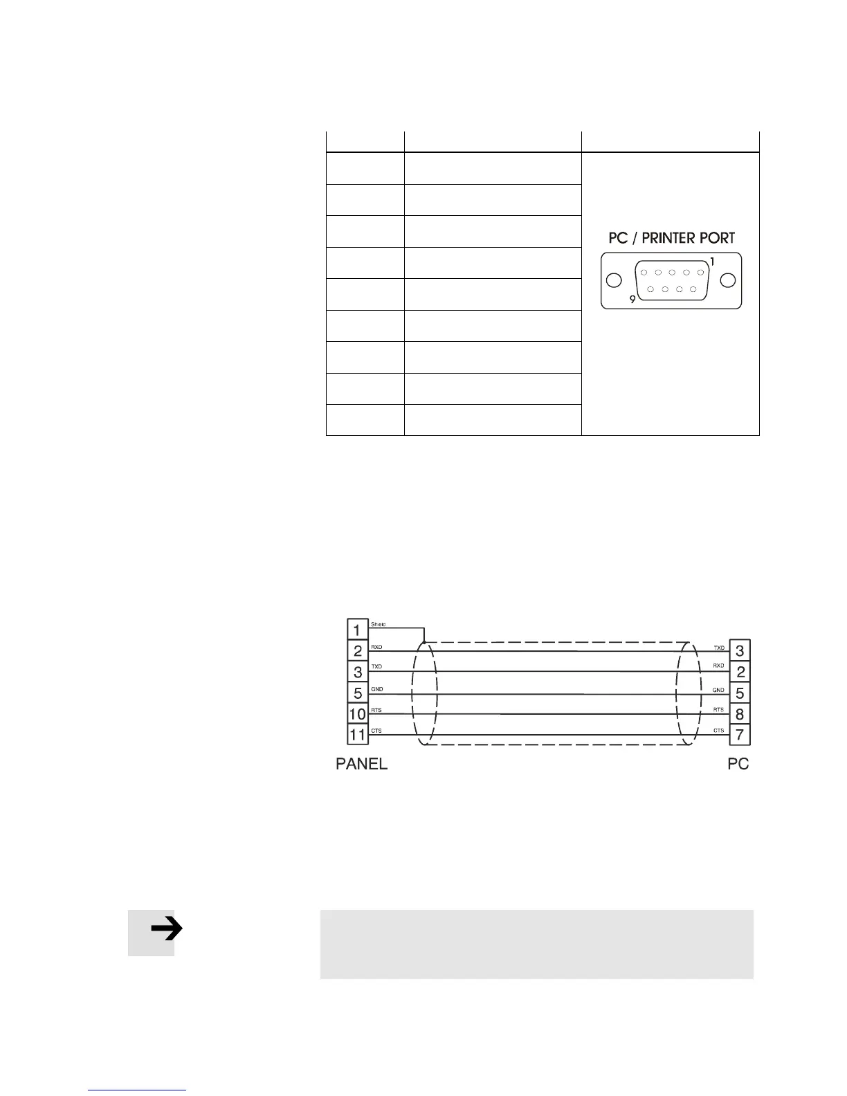
Pin Description
1 GND
2 Reserved
3 TX/CHA-
4 RX/CHB-
5 Reserved
6 +5V output
7 CTS/CHB+
8 RTS/CHA+
9 Reserved
Fig 3/31: PC/Printer Port connector and pin assignment for
FED-770, FED-3000.
Use cable FEDZ-PC-9pin for the connection of an FED-770 and
FED-3000. To connect all the other FEDs to a PC for
programming please use the cable FEDZ-PC. The connector is
a 9-pin sub-D male.
Fig 3/32: Programming cable FEDZ-PC
When the FED HMI is in Operation, you can attach a serial
printer to the PC/Printer Port. The communication parameters
for the printer are defined by the application program (project
file).
Please note
The communication cable to the printer depends on the
communication interface of the printer.
 Loading...