 Loading...
Do you have a question about the Festo VPPM Series and is the answer not in the manual?
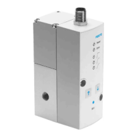
| With accessories | Yes |
|---|---|
| Supply voltage | 24 V DC |
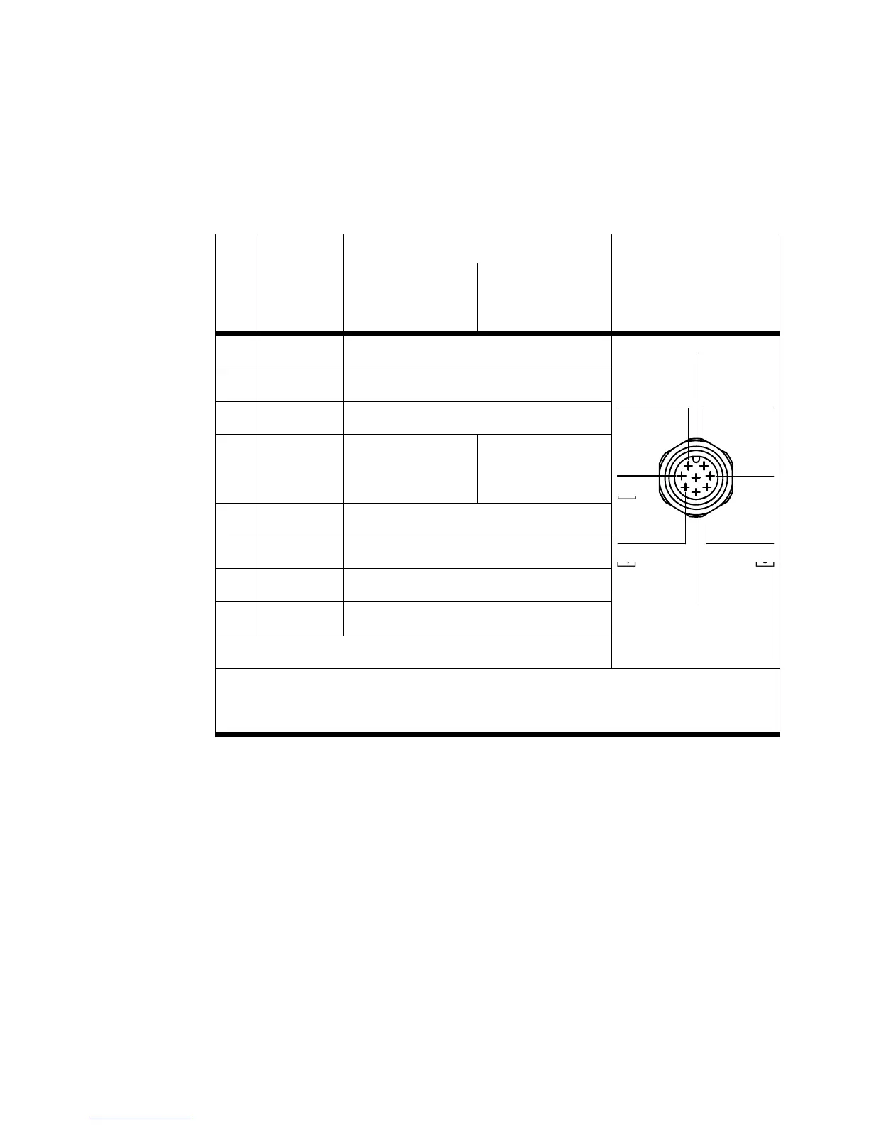
| Electrical connection | M12x1 |
| Operating medium | Inert gases |
| Mounting type | Manifold rail |
| Control characteristic | Proportional |
| Operating voltage | 24 V DC |
| Protection class | IP65 |
| Connection type | M12x1 |
| Type | Proportional pressure regulator |
| Housing material | Plastic |