Material Cutter diameter (mm) Recom
mended
cutting ma
terial
10–25 25–40 40–60
Adjusting wheel setting
Coated
chipboard
6–5 6–3 4–2 HW
Plastic 6–4 5–3 2–1 HW
Alumini
um
3–1 2–1 1 HSS (HW)
Plaster
board
2–1 1 1 HW
Temperature cut-out
The power supply is restricted and the speed
reduced if the motor exceeds a certain temper
ature. The power tool continues operating at re
duced power to allow the ventilator to cool the
motor quickly. The power tool starts up again
automatically once the motor has cooled suffi
ciently.
Restart protection
The built-in restart protection prevents the
power tool from starting up again automatically
if the power is disconnected when the on/off
switch is pressed. In this case, the power tool
must be switched off and then switched back on
again.
Due to the built-in restart protection, the power
tool cannot be switched on and off via an exter
nal switch module.
Brake
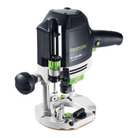
The
OF 1400 EBQ has an electronic brake which
brings the spindle with tool to a standstill within
approx. 2 seconds of the tool being switched off.
7.2 Changing tools
CAUTION
Risk of injury from hot and sharp insertion
tool
► Do not use any blunt or faulty insertion
tools.
► Wear protective gloves when handling an
insertion tool.
To change tools, turn the power tool upside
down.
Inserting the tool
► Insert the routing tool into the open collet
as far as possible or at least up to the
mark on the router shank.
If the collet [3A-2] cannot be seen due to
the union nut [3A-3], the routing
tool
[3A-1] must be inserted into the collet
to the extent that the mark
no longer
projects beyond the union nut.
► Press the switch
[1-14] for the spindle stop
on the right-hand side.
► Tighten the nut [1-15]
using an open ended
spanner (WAF 24).
The spindle stop only jams the motor spin
dle in one direction of rotation. Therefore,
there is no need to use a spanner for tight
ening and loosening nuts. Instead, a ratch
et can be moved backwards and forwards.
Removing the tool
► Press the switch
[1-14] for the spindle stop
on the left-hand side.
► Undo the nut [1-15]
using an open ended
spanner (WAF 24) until you can feel resist
ance. Overcome the resistance by continu
ing to turn the open ended spanner.
► Remove the router.
7.3 Changing the collets
Collets are available for the following shaft di
ameters: 6.0 mm; 6.35 mm; 8.0 mm; 9.53 mm;
10.0 mm; 12.0 mm; 12.7 mm (See Festool cata
logue or online at www.festool.com for the or
der numbers)
► Completely unscrew the nut [1-15] and re
move it together with the collet.
► Only insert a new collet into the spindle if a
nut is fitted and engaged.
► Gently screw in the nut. Do not tighten the
nut if no cutter is inserted.
7.4 Setting the routing depth
The routing depth is set in three steps:
1. Set the zero point, see 7.5
.
2. Specify the routing depth, see 7.6.
3. Clamp the routing depth, see 7.7.
7.5 Setting the zero point
► Release the clamp lever [1-6] so that the
depth stop [1-7]
can move freely.
► Position the router with the router ta
ble [1-9]
on a level surface. Open the rotary
knob [1-5]
and push the power tool down
wards until the cutter sits on the surface.
► Clamp the power tool in this position by
closing the rotary knob [1-5]
.
► Press the depth stop [1-7] against one of
the three fixed stops of the rotatable step
ped stop [1-8]
.
English
17
 Loading...