EasyManua.ls Logo

ffelectronics PYXIS GPS - User Manual

ffelectronics PYXIS GPS
7 pages
Print Icon
To Next Page IconTo Next Page
Loading...
PYXIS GPS
model tracker
Quick Reference Guide V1.5
© ffelectronics August 2022
Introduction
The PYXIS tracker is a free-flight model aircraft recovery system based on the Global Navigation
Satellite System (GNSS), which uses multiple satellite networks such as GPS, GLONASS, Galileo,
Beidou and other regional systems. It does not require the user to transmit any data, operates
independently of any telephone or Internet reception, and works anywhere on earth where there
is free line of sight to four or more satellites.
The PYXIS tracker consists of a receiver (handheld unit) and a beacon (transmitter installed on the
model). Each unit has its own GNSS module which makes it aware of its position. A long-range
radio link allows the transmission of the model's position to the hand unit which, in combination
with the data from a local electronic compass, displays the distance and the bearing in a straight
line to the model, whatever the path taken for the approach.
PYXIS Receiver
Question and Answer IconNeed help?

Do you have a question about the ffelectronics PYXIS GPS and is the answer not in the manual?

Summary

PYXIS Receiver Operation and Features

Switching the Receiver ON;OFF

Procedure for turning the receiver unit on and off using a button.

MicroUSB Charging and Status LEDs

Details on charging the receiver via microUSB and understanding the status LEDs.

PYXIS Beacon and System Operation

How GPS Model Tracking Works

Description of the system's operation for tracking the model's GPS position.

Retrieval Process

Conditions and steps required for successful model retrieval.

System Settings and Configuration

LEARN BEACON ID (LRN BEACON ID)

Procedure to bind a new beacon to the handheld unit receiver.

COMPASS CALIB Menu (e-compass calibration)

Instructions for calibrating the integrated magnetometer and accelerometer sensors.

Tracking and Coordinate Functions

System Batteries Duration and Power Supply

Overview

The PYXIS GPS model tracker is a sophisticated recovery system designed for free-flight model aircraft. It leverages the Global Navigation Satellite System (GNSS), integrating multiple satellite networks such as GPS, GLONASS, Galileo, and Beidou, along with other regional systems. This ensures broad global coverage and reliable positioning. A key advantage of the PYXIS system is its independence from telephone or Internet reception, allowing it to function anywhere on Earth with a clear line of sight to four or more satellites. The system operates without requiring the user to transmit any data, simplifying its use and enhancing privacy.

The PYXIS system comprises two main components: a handheld receiver unit and a beacon, which is installed on the model aircraft. Both units are equipped with their own GNSS modules, enabling them to determine their respective positions. A long-range radio link facilitates the transmission of the model's position from the beacon to the handheld receiver. The receiver then combines this data with information from a local electronic compass to display the distance and bearing to the model, providing a direct path for recovery regardless of the approach taken.

PYXIS Receiver

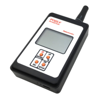
The handheld receiver unit features a clear LCD display and a multifunction keyboard for user interaction.

Display Elements:

  • Direction to model: An arrow indicates the bearing to the model.
  • North direction: A compass rose shows the current north direction.
  • Loudspeaker indicator: Indicates audio alerts.
  • Local GPS status: Shows the GPS acquisition status of the receiver.
    • Solid icon: Position acquired.
    • Flashing and crossed icon: Position acquisition in progress.
  • Beacon ID: Displays the unique identifier of the tracked beacon (e.g., C001).
  • Radio antenna: The physical antenna for radio signal reception.
  • Radio signal strength: An icon indicating the strength of the signal received from the model.
  • Model GPS status: Shows the GPS acquisition status of the beacon.
    • Solid icon: Updated position received.
    • Solid icon (outdated): Outdated position stored.
    • Flashing/crossed icon: Beacon never located previously.
    • Solid icon (on ground): Model is on the ground.
  • Distance to model: Displays the straight-line distance to the model in meters (e.g., 427m, 1253m).
  • MicroUSB recharge plug: Located at the bottom for charging the internal battery.
  • Recharge status LEDs: Red LED indicates charging in progress, green LED indicates charging complete.

Technical Specifications (Receiver):

  • Built-in battery: 1000mAh 1C LiPo.
  • Battery duration: > 20 hours continuously.

Usage Features (Receiver):

  • Switching ON/OFF: Press and hold the power button for approximately 2 seconds.
  • Multifunction keyboard operation:
    • SETUP: Press and hold to enter the setup menu.
    • UP/DN: Press and release to select a menu item.
    • ENTER: Press and release to enter the selected menu.
    • ESC: Press and release to leave a menu.
  • Battery Recharge: The receiver's internal battery can be charged via a standard microUSB socket using a mobile phone charger, computer USB port, microUSB power bank, or car cigarette lighter socket.
  • Compass Calibration: Essential for accurate bearing. It is recommended to calibrate the internal e-compass the very first time the system is used and whenever the handheld unit is moved to fields many kilometers away. The calibration procedure involves rotating the receiver 3 or 4 times for each x, y, z axis in an open area, away from magnetic fields or metal objects. A progress bar is displayed, and the procedure ends automatically after approximately 20 seconds.
  • Holding the Receiver:
    • For retrieval, hold the receiver horizontally. A warning message is displayed if the tilt angle exceeds approximately 40 degrees.
    • For improved radio signal reception from very distant beacons, hold the receiver vertically and lift your arm.

System Settings - Menu Items:

  • LRN BEACON ID (Learn Beacon ID): Allows binding a new beacon to the receiver. The receiver can handle up to 30 beacons.
    1. Enter SETUP > LRN BEACON ID.
    2. Choose a free slot (ID1...ID30).
    3. Confirm with ENTER.
    4. Power ON the new beacon and accept or discard its ID on the LCD.
  • SET ACTIVE ID (Set Active ID): Changes the beacon currently tracked by the receiver.
    1. Enter SETUP > SET BEACON ID.
    2. Choose the desired beacon from the list.
    3. Confirm with ENTER. The active beacon ID will be displayed in the lower left corner of the LCD.
  • COMPASS CALIB (e-compass calibration): Initiates the compass calibration procedure.
    1. Enter SETUP > COMPASS CALIB.
    2. Rotate the receiver as indicated in the manual.
  • DEL BEACON ID (Delete Beacon ID): Deletes all stored beacon IDs.
    1. Enter SETUP > DEL BEACON ID.
    2. Confirm with <YES> or <NO>.
  • TRACKING: This is the default menu entered at power-up. It contains submenus for tracking operations.
    • SET HOME: Stores the current receiver location as "HOME." Useful for returning to the launch position.
      1. Enter SETUP > TRACKING.
      2. Move to SET HOME with UP/DN and confirm with ENTER.
      3. Accept or discard with UP/DN and ENTER, or ESC.
    • GO HOME: Sets the initial position as the destination, guiding the user back to the launch point after model recovery.
      1. Enter SETUP > TRACKING.
      2. Move to GO HOME with UP/DN and confirm with ENTER.
      3. Direction and distance will now refer to the HOME location, and a house icon will be displayed. Remember to set the receiver to track the beacon again after reaching HOME.
    • TRACK BEACON: Allows tracking the beacon whose identifier is the active ID.
      1. Enter SETUP > TRACKING.
      2. Choose TRACK BEACON with ENTER.
    • SHOW COORDIN (Show Coordinates): Displays the actual recorded coordinates (longitude E/W, latitude N/S) in decimal degrees format, which can be used with other location tracking apps like Google Earth or Google Maps.
      1. Enter SETUP > TRACKING.
      2. Move to SHOW COORDIN with UP/DN and confirm with ENTER.

PYXIS Beacon

The beacon is the transmitter unit installed on the model aircraft.

Positioning:

  • The beacon's radio antenna wire should be positioned vertically, protruding from the top of the model's pylon.
  • If the pylon is made of conductive material (e.g., carbon), the narrower upper part of the beacon (approximately 4.5mm high) must completely protrude from the pylon outline to ensure optimal signal transmission.

Bottom Side LED Indications:

  • Red LED: Briefly illuminates during beacon transmission.
  • Green LED: Indicates GPS status:
    • Flashing: GPS acquisition in progress.
    • Solid: GPS connected/locked.
    • OFF: Beacon sleeping or model on the ground.

Technical Specifications (Beacon):

  • Battery: 170mAh 20C LiPo (external power source compatible).
  • Battery duration: > 30-36 hours (estimated).
  • Power Supply Requirements: Can be powered by an external source (e.g., e-timer output, shared LiPo). A red-black soft silicone pigtail is supplied for this purpose.
    • Nominal voltage: 3.7 Vdc (1S LiPo).
    • Absolute maximum voltage: 8.4Vdc.
    • Important: Observe polarity carefully. Inverted polarity or exceeding the maximum allowed supply voltage will cause permanent damage to the beacon.

Beacon Transmission and Power Saving Policy:

  • The beacon incorporates a smart power management scheme.
  • During flight, it periodically transmits updated position information at regular intervals.
  • When the model is placed on the ground for some time, the beacon enters a sleep mode and transmits its fixed position at much longer intervals to conserve power.
  • If the model is moved or lifted, the beacon wakes up and resumes cyclic transmission of position updates.
  • Caution: The system is designed for outdoor operations only. Placing the beacon or handheld unit inside a building, car, or under a large metal cover can lead to rapid battery discharge due to continuous searching for the GPS signal.

System Operation - How GPS Model Tracking Works:

  • While the model is flying, the beacon continuously transmits position updates, ensuring a long-range radio signal without obstacles.
  • If the beacon signal is lost upon model landing (due to uneven ground, tall grass, or obstacles), the handheld unit will point to the last received position.
  • The beacon continues to transmit its position at longer intervals even after landing, allowing the receiver to update the landing position as the user approaches the model.
  • The receiver permanently stores the last known coordinates, even when turned off, enabling recovery at a later time.

Retrieval:

  • Retrieval is only possible if both the local GPS icon and the model GPS icon are displayed solid. In this state, the arrow on the LCD points to the model, and the meter counter shows the straight-line distance. If the model is on the ground, the model GPS icon will display solid.
  • It may take a few minutes for the icons to become solid and the system to operate, depending on sky conditions and satellite positions.
  • If no position updates are received from the beacon (e.g., beacon not powered, discharged battery, or searching for GPS signal), the model GPS icon will be displayed as:
    • Solid with an exclamation mark: Indicates the handheld unit is pointing to an outdated position (the latest received from the same beacon).
    • Flashing with a cross: Indicates the handheld unit has never received position information from that beacon. In this case, no distance is shown, and the arrow points to magnetic North.
  • Recommendation: It is highly recommended to turn on the receiver and ensure it displays a solid model GPS icon before launching the model.

ffelectronics PYXIS GPS Specifications

General IconGeneral
Brandffelectronics
ModelPYXIS GPS
CategoryGPS
LanguageEnglish