Cardiac stimulator 4427 Easypace - Instructions for use
13/40
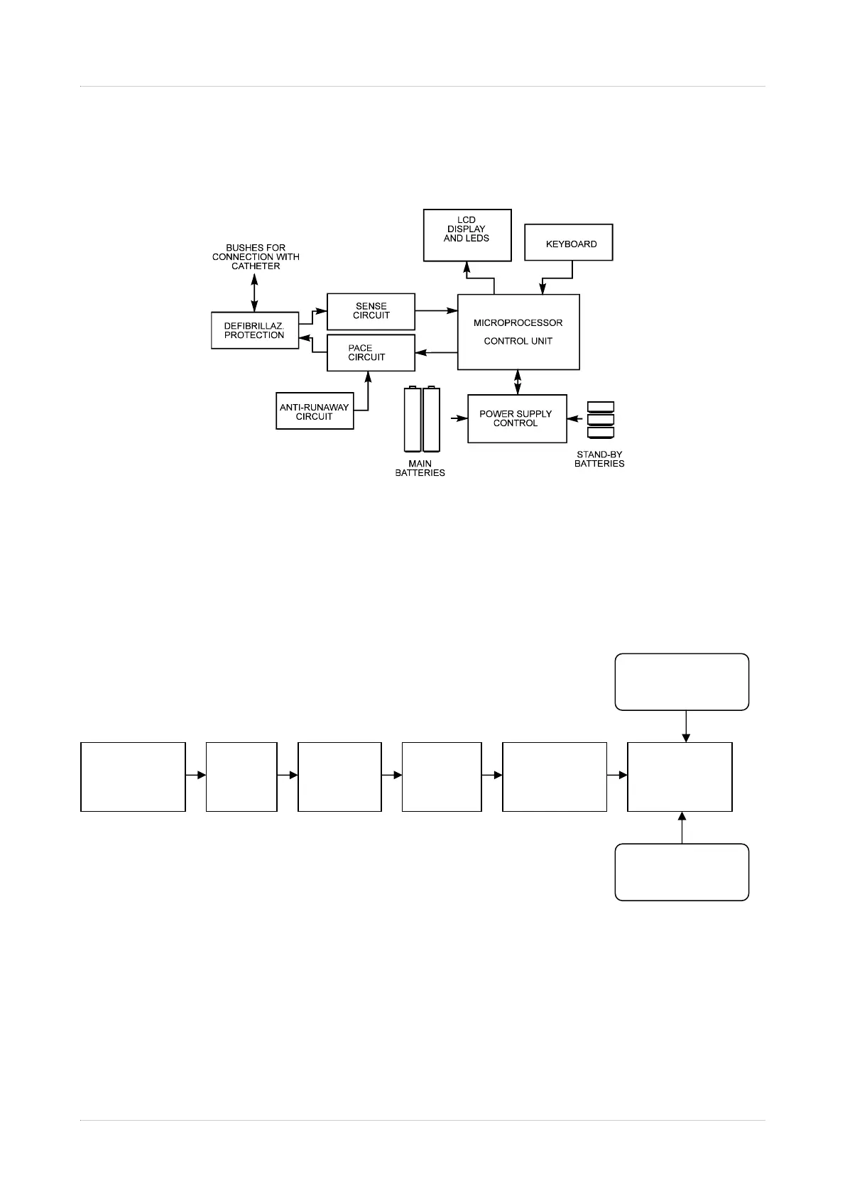
3.1. Block Diagram
The figure below is a block diagram of the heart stimulator 4427 Easypace.
Cardiac signal enters the unit through the lead and the connecting socketes. A suitable
circuit provides for the protection against the defibrillator discharge.
The sense channel consists of a chain of amplifiers and filters - schematically illustrated in
the figure below - for the cardiac signal acknowledgement:
The current (mA) controlled output stimulation is governed by the microprocessor
according to values entered via the keyboard and visualised on the display. The
stimulation impulse is followed by a short period of electrode depolarisation obtained
through a short-circuit of the two catheter poles.
Load
Resistance
& Clamp
Buffer
Filtering
Blanking
Amplitude
Adjustment
Threshold
Detector
From MCU
To MCU