- 17 -
English
8. Make sure the assembly is correct and that there
are no leaks before mounting the casing back on.
9. Record the replacement in the maintenance table
of this manual or by using the RO-Check app.
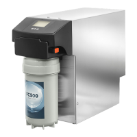
Dismantling procedure for the vessel unit
1. Vessel
2. L shaped connector
3. Locking clip
4. Permeate connector
To dismantle the vessel unit, simply remove the con
-
nection clip between the permeate duct (4) and the
vessel (1) and remove the vessel unit.
To reassemble the vessel unit, position its dovetails in
the casing slits, move delicately downwards ensuring
the L-shaped connectors and permeate connectors
are correctly inserted. Having done this, position the
locking clip (3) again.
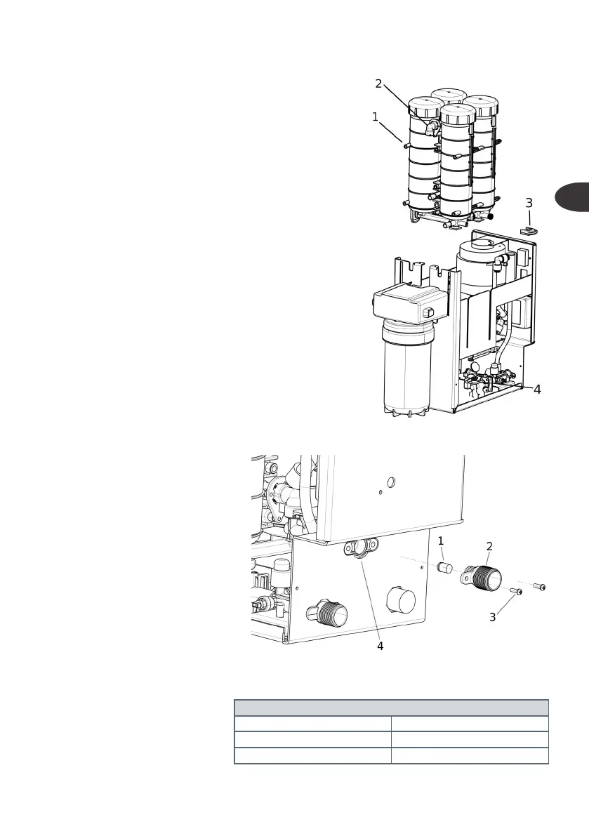
Replacement procedure for the ow restrictor
1. ow restrictor
2. drainage outlet tting
3. screws
4. drainage manifold
To replace the ow restrictor, un
-
screw the screws (3), remove the
tting (2).
Remove the restrictor (1) from the
tting and place in the new tting.
Attention! Observe the correct
direction, O-ring outside the tting
(see image).
Re-assemble the screws, fasten
with reversible thread-locker.
FLOW RESTRICTOR TABLE
200 Blue
400 Purple
500 Grey