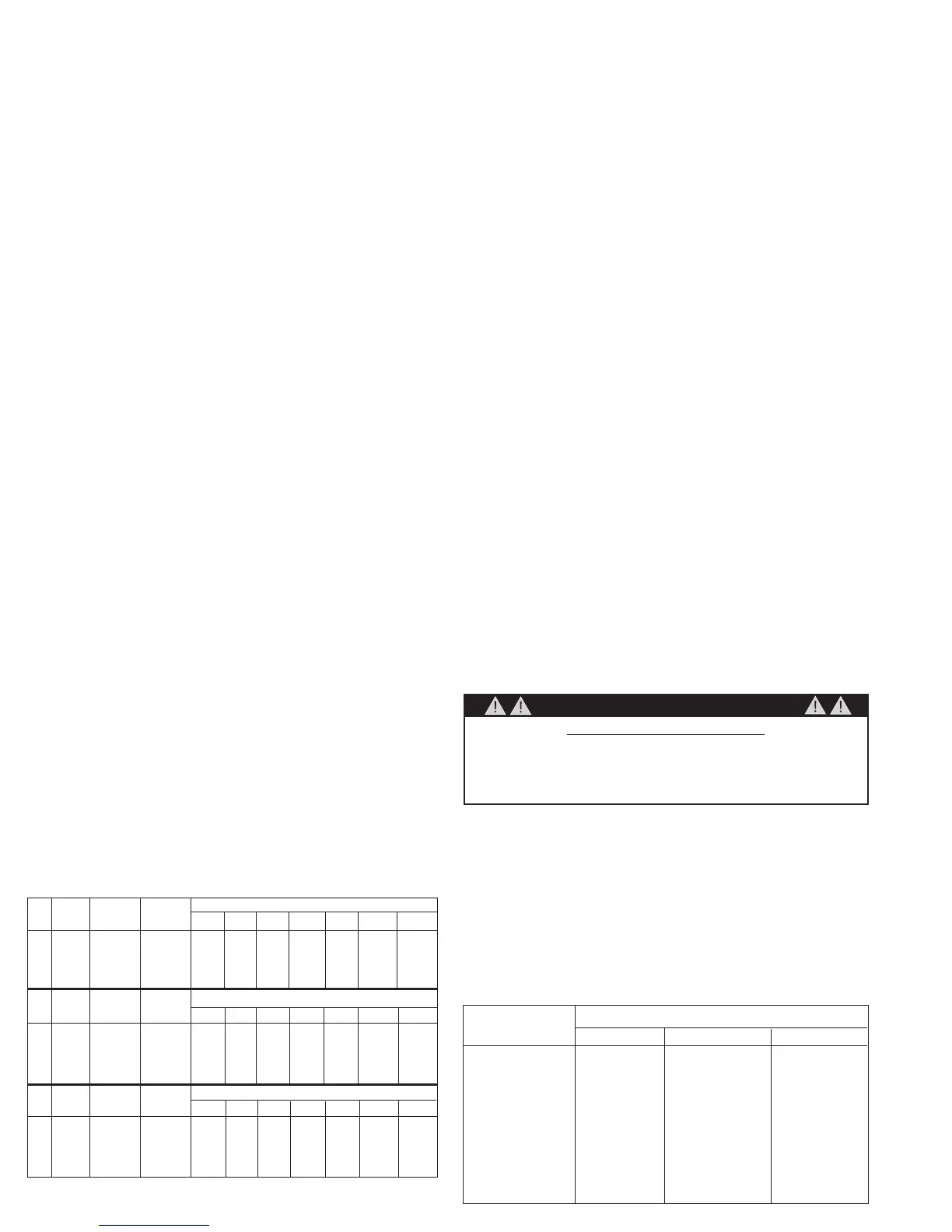
EasyManua.ls Logo

Fimco TR-30-EX - Page 2

Fimco TR-30-EX
4 pages
Print Icon
To Next Page IconTo Next Page
To Previous Page IconTo Previous Page
Loading...
Page 2

   
   
        
          
        
        
  
  
 
        
          
        
        
  
  
 
        
          
        
        
Tip Chart
 
   
   
   
   
   
   
   
   
   
   
   
Speed Chart

the trailer frame.
          
best as possible.


wheel in place.

         
hardware to secure the boom in place.


      


or the "hot" connection on a switch or to the ammeter. The
brown wire may be grounded or connected to the negative


thread it onto the drain bung located at the lower rear end

        
           
handgun storage.
Read the operating instructions and then run the sprayer
using only water for testing. Initially begin spraying by clos
        
valve to the boom. This will enable the air in the line to be
eliminated through the tips, while building pressure. When


the spraying operation.
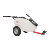
OPERATION
This sprayer is designed to be towed behind a garden
tractor.
NOTE: Make sure the tires are inated to 30 P.S.I. prior
to usage!

the strainer and to the pump. The pump forces the solution
under pressure to the handgun or boom nozzles.
The pump has a pressure switch which will shut the pump





vary when turning the nozzle end.

         
concrete surface. Raise the boom to get more spray pattern
overlap if desired.
WARNING: Some chemicals will damage the pump valves if

  

manufacturers instructions on disposal of all waste water
from the sprayer.
CALIBRATION
Chemical labels may show application rates in gallons per

feet. You will note that the tip chart shows all three of these
rating systems.
PRESSURE SWITCH OPERATION
Pressure switch is pre-set at the factory. Improper
adjustment of the pressure switch, may cause severe overload or
premature failure. If the pump is subjected to rapid cycling during
normal operation, or infrequent periods, damage may occur.
CAUTION

Related product manuals