3. Grasp the bottom of the rear cover and lift it free of the
case.
4. Lift the battery from the case, and carefully disconnect
the battery connector leads.
5. Snap the battery connector leads to the terminals of a
new battery and insert the battery into position. Dress
the battery leads so that they will not be pinched
between the case bottom and the case top.
6. Repla
c
e the rear cover, ensuring it slips beneath the
holddown lip (next to the jaw
s
) and fits securely into
position.
7. Reinstall the three securing screws.
If this Meter is not be used for periods of longer than 60
days, remove the battery and store it separately.
98
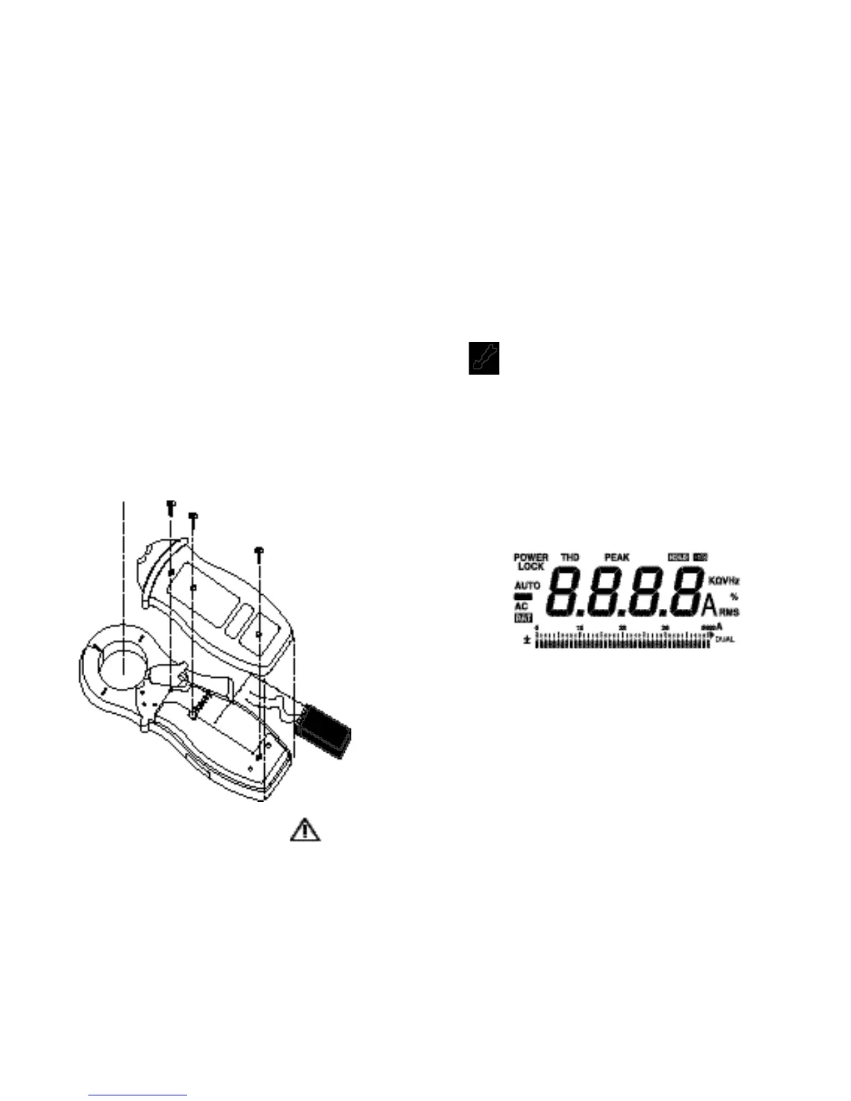
Figure 2. Battery Replacement
5.2 Notes
For taking full advantage of this Meter’s capabilities, read
completely, in sequence, each of the following pages. It is
not necessary to make a measurement to learn how to use
this meter. Take the time to read this section completely
before attempting any meter applications be
c
ause this
meter has many features and operating sequences that are
not readily apparent.
WARNING!
MOST OF THE TYPICAL APPLICATIONS ARE
EXPOSED TO LETHAL VOLTAGES. BE CAUTIOUS
WHEN TAKING MEASUREMENTS.
B
EFORE THE
METER IS CONNECTED TO ANY CIRCUIT, REVIEW
THE SAFETY INFORMA-TION. ALWAYS KEEP YOUR
HANDS BEHIND THE METER’S HAND GUARD.
5.3 Power Up/Self Test
Press and hold the ON OFF pushbutton in order to power
up and initiate self test. This meter beeps and all LCD
segments will turn on (some segments have nothing to do
with this Meter.) as part of a self-test routine. Observe a
bar graph pointer blinks to indicate the battery
c
ondition
while st
i
ll pres
s
i
ng the ON OFF pushbutton. The “Off-
Scale” arrow blinks for a battery life in excess of 40 hours
and a corresponding bar graph pointer blinks for a battery
life of less than 40 hours. Read the scale as 0 to 40 hours
for this battery test. A po
i
nter under the 3 (6 is not
displayed) on the scale, for example, represent
s
approximately 30 hours of remaining battery life.