16 17
4.3 Diode Test & Microwave Didoes
Diode test lets you check didoes, transistors, and other
semiconductors for opens, short, and normal operation. NEVER
CONNECT THE TEST LEADS TO A SOURCE OF VOLTAGE when
the rotary switch is set to .
• In diode test, drop voltage in the forward direction is displayed when
diode is connected in the forward direction. For a germanium diode,
the typical forward voltage is about 0.4V and in case of a silicon
diode, about 0.6V.
• Judge the semiconductor device as follows:
It the digital reading in one direction shows a value and the reading
in reverse direction shows an overload (
I
...
). the device is good.
If the digital reading is the sa
m
e in both directions, the device is
probably shorted.
If the display reads
I
. . .
in both directions, the device is probably
open.
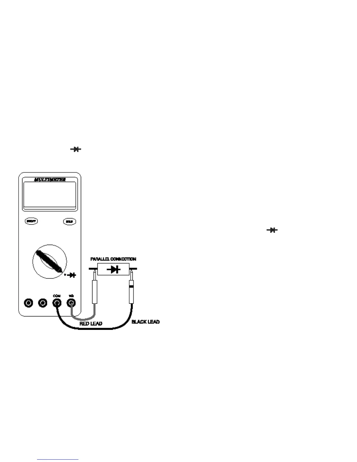
4.3.1 Diode Test
Follow these steps to check a diode.
1. Set the Function switch to the “ ” position.
2. Insert the black test lead into the “COM” input terminal and the red
test lead into the “VΩ” input terminal.
3. Touch the red test lead to the Anode (+ side. non-banded end) and
the black test lead to the Cathode (- side. banded end).
4.
If the diode is good, the reading should indicate 0.3V to 0.8V on the
LCD.
5. Reverse the red and black leads on the diode, if the LCD reads
I
...
(the overload sign) the diode is good.
NOTE: A defective diode will read
I
...
( the overload sign) or 0.00
no matter how the test leads are connected.
 Loading...