4 5
WARNING!
OBSERVE ALL SAFETY PRECAUTIONS WHEN MEASURING
HIGHER VOLTAGES AND/OR CURRENTS. TURN OFF POWER TO
THE CIRCUIT UNDER TEST, SET THIS METER TO THE DESIRED
FUNCTION AND RANGE, CONNECT THE TEST LEADS TO THIS
METER AND THEN TO THE CIRCUIT UNDER TEST. REAPPLY
POWER. IF AN ERRONEOUS READING IS OBSERVED,
DISCONNECT POWER IMMEDIATELY AND RECHECK ALL
SETTINGS AND CONNECTIONS.
Safety Tips:
•
Do not try to measure any voltage that exceeds 1000V DC or 750V
AC RMS.
•
Voltages above 60V DC or 25V AC RMS may constitute a serious
shock hazard.
•
Do not attempt to use this Meter if either the Meter or the test leads
have been damaged.
•
Turn off power to the circuit under test before cutting, unsoldering, or
breaking the circuit. Small amounts of current can be dangerous.
•
Disconnect the live test lead before disconnecting the common test
lead.
•
When using the test leads, keep your fingers away from probe
contacts. Always grip behind the finger guards on the probes.
•
Use a current clamp if measuring any current above 10 Amps.
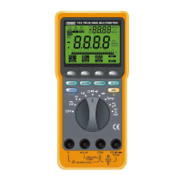
1 – DIGITAL DISPLAY. Digital readings are displayed on a 2000
count display with polarity indication.The display updates three
times per second.
2 – . Selects meter’s power ON or power OFF.
3 – . Freezes reading in digital display.
4 – ROTARY SWITCH. Describes functions that are selected by
setting the rotary switch.
V Volts ac V Volts dc A Amperes ac
A Amperes dc
Ω
Resistance Continuity Test
Diode Test
5 – . The maximum current that you can measure at this
terminal is 10 Amps DC/AC.
This terminal is fuse
6 – . Refer to the user’s manual before using this Meter.
7 –
A
(Amperes Input Terminal). The red test lead is plugged into
this terminal for measuring current on the 10A AC or DC current
functions.
8 –
mA
µ
A
(Milliamp/Microamp Inpu
t
Terminal). The red test
lead is plugged into this terminal for measuring mA or µA on
either AC or DC current functions.
10A MAX
FUSED
3. EXPLANATION OF CONTROLS AND INDICATORS