4. Snap the front and rear housing back together and reinstall the
screws.
5. Reattach the rubber boot.
NOTE: When servicing the Meter, use only th replaceable
parts specified.
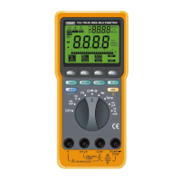
BT1 .............Battery, 9 Volts
F11 ............. Fuse: 1A, 600V RMS
F2 ............... Fuse: 15A, 600V RMS
TL1 ............. Test Lead Set
TP1A .......... K-type Thermocouple Adapter
C2Y ............ Rubber Boot (Yellow)
TP1 .............K-type Thermocouple [Optional]
RS50 ...........RS-232C Interface Cable (1.5m) [Optional]
RSA50.........RS-232C Interface Adaptor [Optional]
DS50 ...........RS-232C Software Dise [Optional]
7. ACCESSORIES
48 49
8.1 Specifications
Accuracy is given as ± ([ % of reading] + [number of least
significant digits]) at 18°C to 28°C with relative humidity up to
80%, for a period of one year after calibration.
FUNCTION
RANGE RESOLUTION ACCURACY
REMARKS
Input Impedance:
400mV
0.1mV
> 100MΩ
DC V
4V 1mV ± (0.3% + 2 dgts) Approx. 11MΩ
40V 10mV Approx. 10MΩ
400V 0.1V
1000V 1V ± (0.75% + 3 dgts)
DC A
400µA
0.1µA
Voltage Drop:
4000µA 1µA ± (0.5% + 1 dgt) 100µVmA
40mA 0.01mA 1.2mV/mA
400mA 0.1mA
4A
0.001A ± (1.0% + 5 dgts)
75mV/A
10A 0.01A
400Ω 0.1Ω ± (0.5% + 10 dgts) Open Circuit
Ohms 4KΩ 1Ω Voltage:
40KΩ 10Ω
400K
Ω
0.1K
Ω
± (0.5% + 3 dgts) < 1.2V
4MΩ 1KΩ
40MΩ 10KΩ ± (1.2% + 8 dgts)
8. SPECIFICATIONS
 Loading...