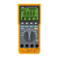
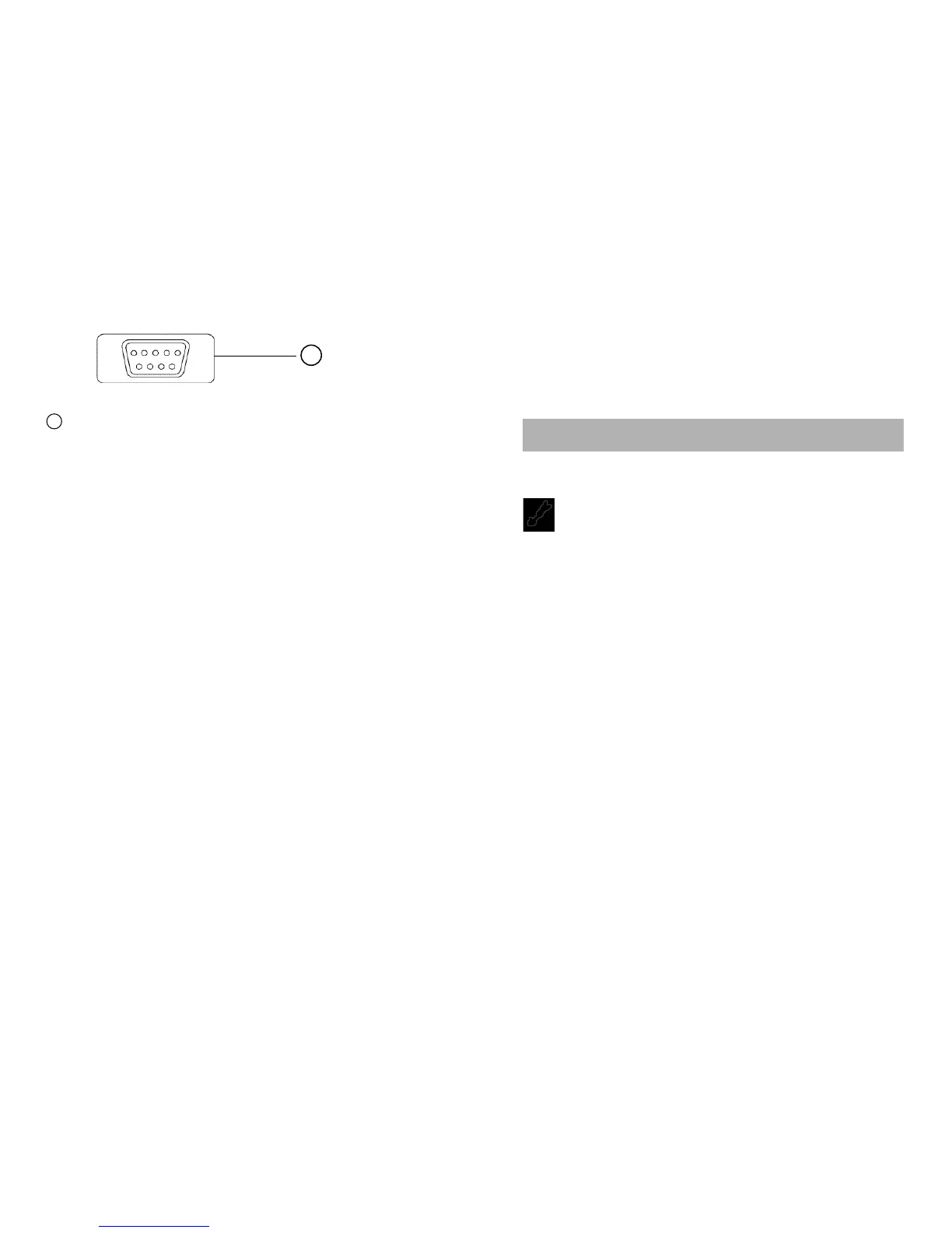
RS-232C TERMINAL. The standard D9 male connector of the
RS-232C serial cab
l
e (RS50) is plugged into this terminal
when interfacing to a PC. The RS-232C serial cable is
optional.
Auto-Power-Off Mode
If this Meter
i
s
on and inactive for approximately 30 minutes (1
hour in the Recording mode), this Meter will automatically switch to
Auto-Power-off Mode. To resume operation, turn the rotary switch
back to the OFF position and then turn Meter on again. To disable
the Auto-Power-Off Mode, turn the rotary switch from OFF to any
function (ON) position while holding down the HOLD button.
Using Test Leads
Use only the same type of test leads as are supplied with the
Meter. These test
l
eads are rated for 1200 vo
l
ts. Although these
test leads are rated for 1200 volts, do not try to measure any
voltage greater than 1000 volts DC or 750 volts AC.
NOTE: In some DC and AC voltage ranges with the test leads
not connected to any circuit, the display may show
fluctuating readings due to the high input impedance.
This is normal. When you connect the test leads to a
circuit, a real measurement appears.
42
BOTTOM CASE
42
16 17
Using Holster and Stand
The Meter comes with a protective holster that absorbs shocks
and protects the Meter from rough handling. The ho
l
s
ter is
equipped with a stand rest.
4.1 Measuring Voltage
WARNINGS!
TO AVOID THE RISK OF ELECTRICAL SHOCK AND
INSTRUMENT DAMAGE, INP
U
T VOLTAGES MUST NOT
EXCEED 1000V DC OR 750V AC (RMS). DO NOT ATTEMPT TO
TAKE ANY UNKNOWN VOLTAGE MEASUREMENT THAT MAY
BE IN EXCESS OF 1000V DC OR 750V AC (RMS).
THIS METER IS DESIGNED FOR MEASUREMENT IN WEAK
CURRENT CIRCUITS. DO NOT USE IT FOR STRONG
CURRENT CIRCUITS (POWER LINE IN FACTORIES AND SO
ON HAVING LARGE CURRENT CAPACITY). USE IN STRONG
CURRENT CIRCUITS IS VERY DANGEROUS BECAUSE
SURGE VOLTAGE IN FAR EXCESS OF RATING IS OFTEN
APPLIED TO THEM.
NOTE: When taking voltage measurements, this Meter must
be connected in PARALLEL with the circuit, or circuit
element under test.
4. BASIC ELECTRICAL TESTS AND MEASUREMENTS
 Loading...