• In 400mV range, displayed value may fluctuate when
disconnecting input terminals. This is normal.
• AC voltage measuring circuit
i
n this Meter is of root-
meansquare (True-RMS) value system so this Meter can
accurately measure AC voltage of non-sinusoidal wave forms
including harmonics caused by various non-linear loads.
For an AC voltages (or
c
urrent) Meter, CREST FACTOR
expresses
i
ts ability to respond to non-sinusoidal waveforms.
[CREST FACTOR is defined as the ratio of the peak voltage of
an AC waveform to its RMS value.] The AC crest factor of this
Meter is 3 for the frequency range of 45Hz to 1KHz.
19
18
• To improve the accuracy of DC voltage measurements taken in
the presence of AC voltages (such as, measuring the DC
voltage of an amplifier in the presence of an AC
s
i
gnal),
measure the AC voltage first. Note the
j
ust measured AC
voltage range and select a DC voltage range that is the same or
higher than the AC voltage range. This method
i
mproves the
DC voltage accuracy by preventing the input protection circuits
from being activated.
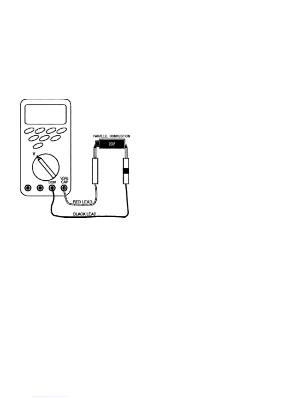
4.1.1 Measuring DC Volts
Follow these steps to measure DC volts.
1. Set function and range switch to the desired DC V range. If you
do not know the value of the voltage to be measured, always
start with the highest range and reduce the setting as required
to obtain a satisfactory reading.
2. Plug the red test lead into the “VΩHz CAP” input terminal and
the black lead into the “COM” input terminal of the instrument.
3. Disconnect the power from the circuit to be tested.
4. Connect the test leads to the circuit to be tested.
5. Reapply power to the circuit, the measured voltage will appear
on the display of the instrument.
6. If the red test lead is connected to the negative (or lower
voltage) side of the cir
c
uit, a minu
s
sign will appear on the
display, at the left.
7. Disconnect power to the circuit before removing the test leads
from the circuit.
 Loading...