Follow these steps to measure temperature.
1. Set the rotary switch to the “TEMP” position.
2. Plug the thermocouple adapter into the COM input terminal and
the TEMP input terminal observing the proper polarity.
3. Plug a K-type thermo
c
ouple probe connector into the
thermocouple adapter observing the proper polarity.
4.
Read the temperature on the LCD.
5.1 Introduction
RS-232C is an EIA-defined standard for a serial communications
interface commonly u
s
ed between computers, term
i
nals, and
modems.
This Meter is capable of RS-232C interface with a DOS computer
by using its bi-directional RS-232C serial interface cab
l
e and its
DOS software supp
l
ied as optional accessor
i
es along with this
Meter.
5.2 Interfacing the Meter with a Personal Computer
Follow these steps to interface the Meter with a DOS computer.
1. Connect the RS-232C cab
l
e to the computer’s 25-pin serial
port. Plug the D9 male connector into the RS-232C terminal on
the back of the Meter.
The RS-232C driver is powered by ± 12V supplied from the
interfaced computer through “DTR” and “RTS” pins of the D25
female connector.
36 37
5. RS-232C INTERFACE
2. Turn on the Meter and Press the RS-232C (REL) button for 2
seconds to activate the RS-232C communicat
i
on. The
s
ymbol
‘RS-232C’ will appear on the LCD.
3. Load the DOS software diskette, which is optionally supplied for
the Meter, on the computer. This software requires a VGA or
upper-class monitor.
4. Copy the files from the software diskette to the computer’s hard
disc to make a back-up copy.
5. Run the execution f
i
le loaded from the DOS software dis
k
ette
by typing the name of the execution file at the DOS prompt.
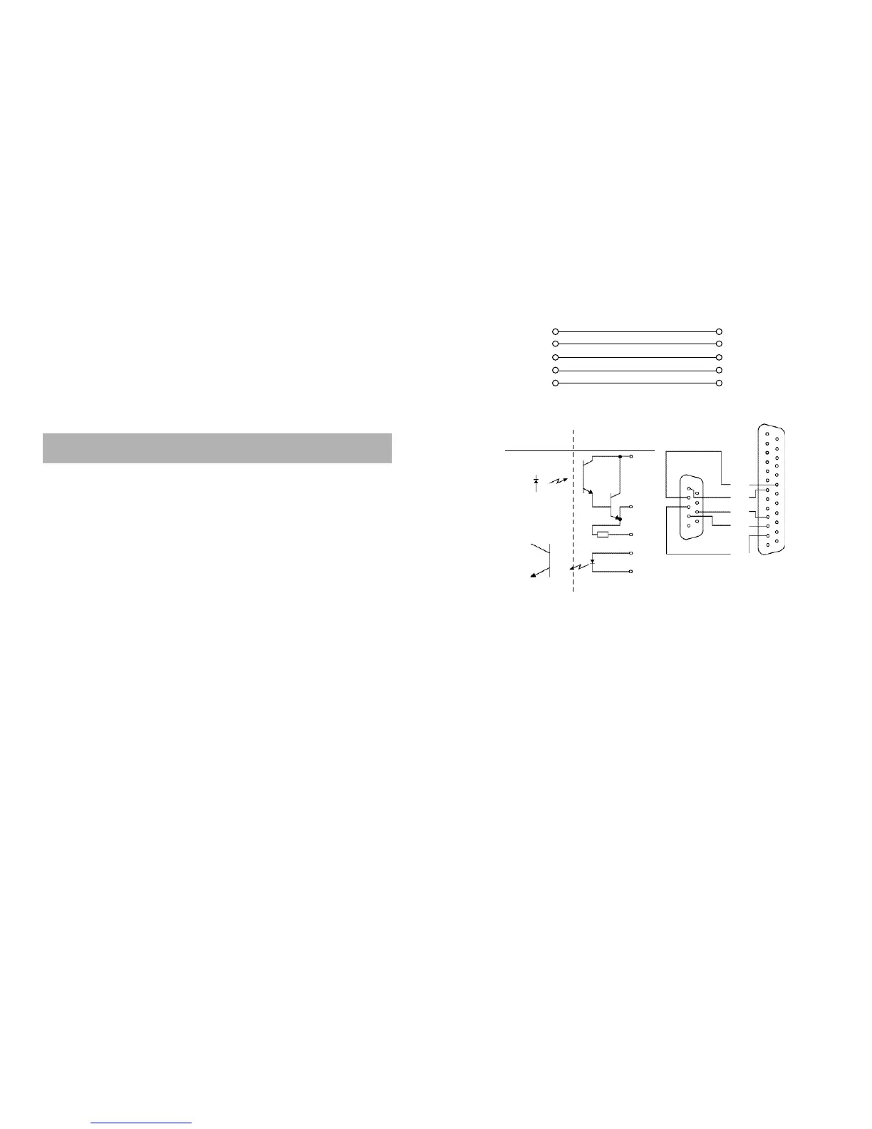
The RS- 232C connector’s pin configuration is as follows
< DMM > < Computer >
2 3 RXD
3 2 TXD
4 20 DTR
5 7 G N D
7 4 RTS
COMPUTER SIDE
D T R
R X D
R T S
T X D
G N D
9 P I N
2 5 P I N
T X D
R X D
R T S
G N D
D T R
5
1
9
6
1 3
2 5
1 4
1
MICOM SIDE
T X D
R X D
 Loading...