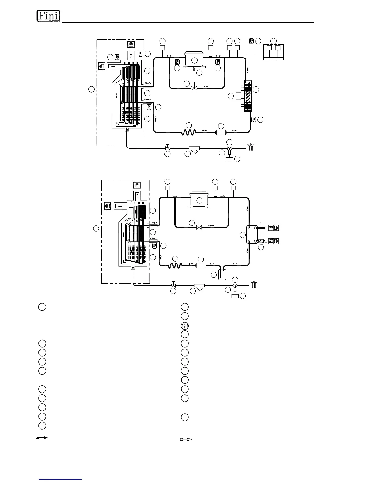
5.3 FLOW DIAGRAM (Air-Cooled)
12.1
T6
15
EC
1413
16
17
1
12
1c
T1
1b
1a
P
B
3 54
P
11
10
7
6
T
S
9 M
8
P
VA
T3
T2
12.1
12.1
T5
12.1
T4
12.1
12.1
T7
25
5
V1
P
V2
P
2
480-810
D
G
F
0
0
1
1
5.4 FLOW DIAGRAM (Water-Cooled)
10
11
6
1
7
12
P
2
P
B
4
T1
A
1a
1b
1c
13
16
EC
15
14
T
S
3
17
18
19
20
D
G
F
0
0
0
2
1
Alu-Dry Module
11
Capillary tube
a - Air-to-air heat exchanger
12
T1 Temperature probe (DewPoint)
b - Air-to-refrigerant exchanger
Temp. Probes T2-T8 → DMC20 (if installed)
c - Condensate separator
13
Condensate drain service valve
2
Refrigerant Pressure Switches P
B
14
Y-shaped condensate drain strainer
3
Safety thermo-switch Ts
15
Condensate drain solenoid valve
4
Refrigerant Pressure Switches P
A
16
Coil for cond. drain solenoid valve
5
Refrigerant pressure-switch (fan) P
V
17
EC = Electronic control instrument
P
V1
- P
V2
(RD 480-810)
18
Condenser (Water-Cooled)
6
Compressor
19
Condenser water regulating valve (water-Cooled)
7
Hot gas by-pass valve
20
Liquid receiver (water-cooled)
8
Condenser (Air-Cooled) …
9
Condenser fan
25
Compressor crankcase heater
10
Filter Drier