40069 Zola Predosa (BO) - ITALY
info@finicompressors.it
- EN -
5.13 REFRIGERANT PRESSURE SWITCHES P
A
– P
B
– P
V
As operation safety and protection of the dryer a series of pressure switches are installed in the gas circuit.
PB :
Low-pressure controller device on the suction side (carter) of the compressor, is enabled only if the
pressure drops below the pre-set value. The values are automatically reset when the nominal
conditions are restored.
Calibrated pressure : R 404 A Stop 1.0 barg - Restart 5.0 barg
PA :
This high-pressure controller device, located on the pushing side on the compressor, is activated
when the pressure exceeds the pre-set value. It features a manual-resetting button mounted on the
controller itself.
Calibrated pressure : R 404 A Stop 32 barg - Manual reset
PV : RD80-360 Fan control pressure switch located on the pushing side on the compressor. It keeps the
condensation temperature/pressure constant within preset limits (Air-Cooled).
Calibrated pressure :
RD 185-410
R 404 A
Start 20 barg (45°C) - Stop 18 barg (40°C) - Tolerance ± 1 bar
PV1 :
RD480-810 Fan control pressure switch located on the pushing side on the compressor. It keeps
the condensation temperature/pressure constant within preset limits (Air-Cooled) – Low Speed.
Calibrated pressure : R 404 A
Start 21 barg (47°C) - Stop 18 barg (41°C) - Tolerance ± 1 bar
PV2 :
RD480-810 Fan control pressure switch located on the pushing side on the compressor. It keeps
the condensation temperature/pressure constant within preset limits (Air-Cooled) – High Speed.
Calibrated pressure : R 404 A
Start 23 barg (51°C) - Stop 20.5 barg (46°C) - Tolerance ± 1 bar
5.14 SAFETY THERMO-SWITCH T
S
1
2
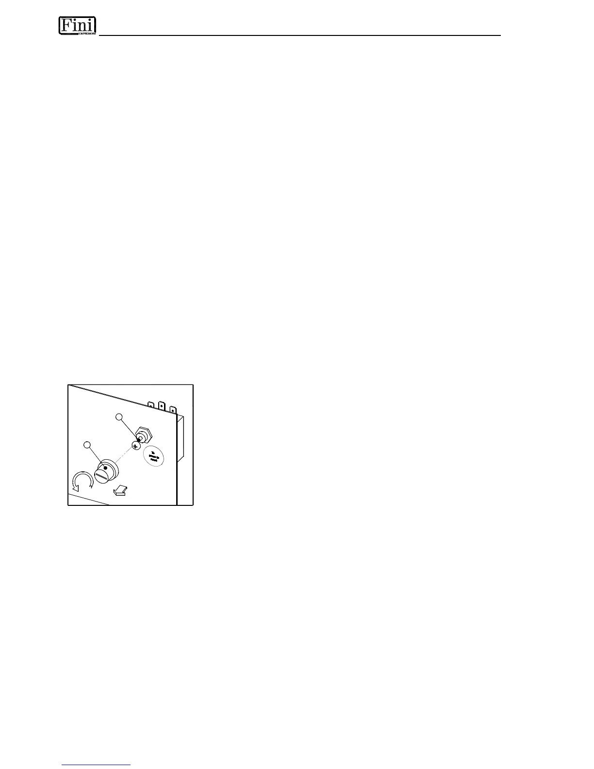
To protect the operating safety and the integrity of the dryer, a thermo-
switch (TS) is installed on the refrigerant gas circuit. The thermo-switch
sensor, in case of unusual discharge temperatures, stops the refrigerating
compressor before it is permanently damaged.
Manually reset the thermo-switch only after the nominal operating
conditions have been restored. Unscrew the relative cap (see pos.1 in the
figure) and press the reset button (see pos.2 in the figure).
TS setting : temperature 100 °C (+2 / -2 °K)
5.15 COMPRESSOR CRANKCASE HEATER
At low temperatures oil can more easily be mixed with the refrigerant gas. So, when the compressor starts,
oil can be drawn into the refrigeration circuit and liquid hammering could occur.
To prevent this, an electrical resistance heater is installed in the suction side of the compressor. When the
system is powered and the compressor is not running, this heater keeps the oil at the correct temperature.
This heater is controlled by a thermo-switch which prevents overheating the oil.
NOTE : The heater must be powered at least a couple of hours before the start up of the refrigeration
compressor.