In case of heavily polluted inlet air (ISO 8573.1 class 3.-.3 or worse quality), we recommend the
additional installation of a pre-filter (5 micron minimum) to prevent a clogging of the heat
exchanger.
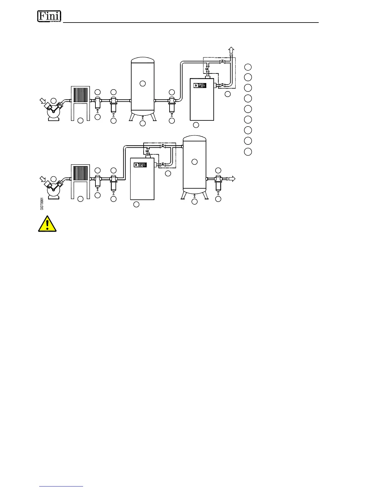
Type A installation is suggested when the compressor operates at reduced intermittence and the total
consumption equals the compressor flow rate.
Type B installation is suggested when the air consumption can consistently change with peak values highly
exceeding the flow rate of the compressors. The capacity of the tank must be sized in order to compensate
eventual instantaneous demanding conditions (peak air consumption).