Page 10
Installation
WARNING! If you do not follow these instructions exactly, a re or
explosion may result causing property damage, personal injury or loss of life.
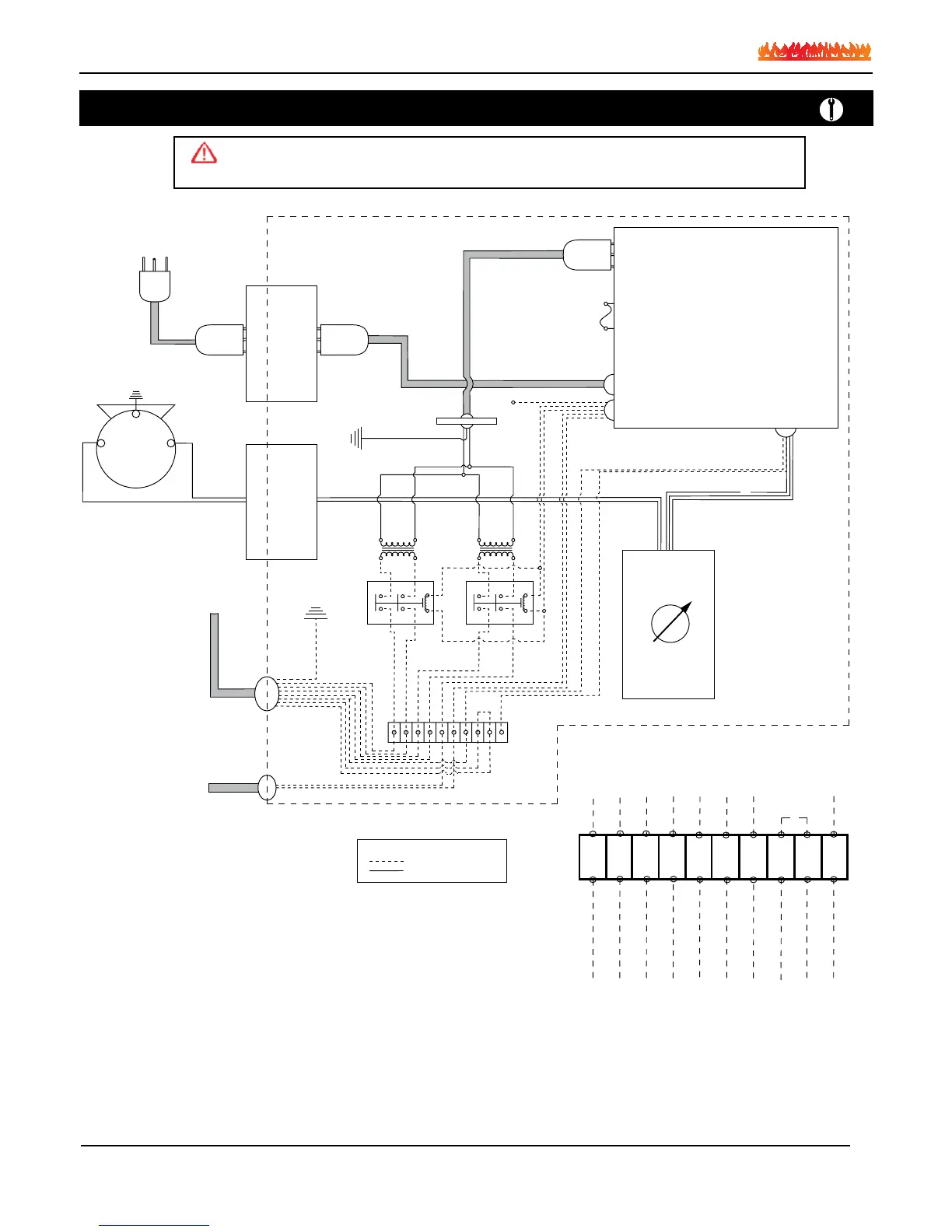
First Burner: 1,2 Black-White
Second Burner: 3,4 Blue-Yellow
Wall Switch: 6,7 Black-White
Air Priority Switch: 9,10 Orange-Red
Green is Ground
110V Power Supply
Post Purge Control
6 Amp 110V Fuse
110V Motor
Bk
W
G
Bk
W
G
R
R
Motor Speed
Control
Bk
W
110V
24V
110V
24V
BB
R
BkW
Y
R1
Y Y Y
Bk W B Y
Bk
P
G
O
R
To Fireplace
Post Purge Control
R2
BW
To Wall
Switch
Legend
Denotes Low Voltage
Denotes Line Voltage
Blk / Wht
Pk
Brn
Valve 1
Valve 2
Wall Switch
Air Proving
Switch
Org
Red
Red
LVT
LVT
Wht / Blk
Red
Blu
Blu
Blk / Yel
Blk / Wht
Wht / Blk
Blu / Yel
Yel
Yel
Yel
Yel
Relay
Relay
Wall Switch
Jumper
1 2 3 4 5 6 7 8 9 10