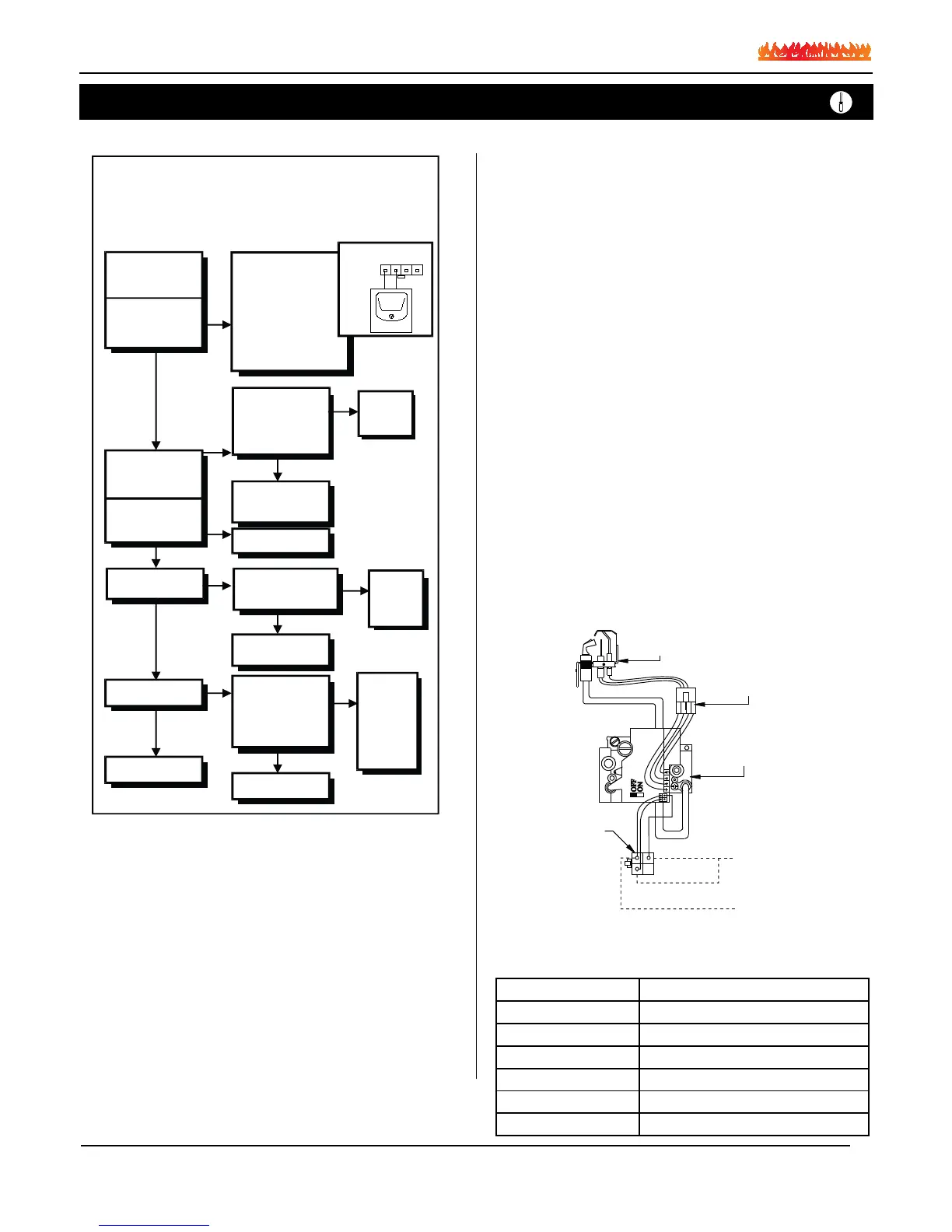
Troubleshooting
- Turn Gas Supply Off
- Set thermostat to
call for heat
SV9500 / SV9600
is powered
(24VAC nominal)
HSI
Terminals
NOTE:
Before Troubleshooting, Familiarize Yourself With
The Startup And Checkout Procedure.
START
HONEYWELL SV9500 /9600
Troublshooting Sequence
INSET
NO
CHECK:
- Line voltage power
- Low voltage transformer
- Limit Controller
- Thermostat
- Wiring
- Air proving switch on
combustion air blower system
-Vent damper (if used) is open
and end switch made
NO
NO
YES
NO
YES
Unplug Pilot Burner Cable,
Measure Voltage at
SV9500/SV9600 HSI
Terminals (24VAC
Nominal, see INSET)
Replace
SV9500/
SV9600
Igniter warms up and
glows red.
YES
YES
NO
YES
NO
Pilot Valve opens.
Replace Igniter /
Flame Rod Assembly
Replace SV9500/SV9600
NO
NO
YES
YES
Turn gas on.
Pilot Burner Lights?
Main Valve opens?
SYSTEM OK
Discard old Igniter /
Flame Rod Assembly
Measure Volume to
SV9500 / SV9600 Voltage
must be at least 19.5 VAC
Check
Transformer
Line Volt
Supply
Replace Igniter /
Flame Rod Assembly
Replace
SV9500 /
SV9600.
Save old
Igniter/ Flame
Rod Assembly
for service.
Replace Igniter / Flame
Rod Assembly and retain.
Restart troubleshooting
Sequence. Does main
valve open?
Maintenance
If your fireplace still does not operate correctly, consult your dealer or
the manufacturer. All service and repairs should be performed by
a qualified agency. All spare parts, optional fans, and optional trim
finishes are available from your local dealer or the manufacturer.
Gas Control Valve
Figure 11. Honeywell SV9501 gas valve.
Troubleshooting the Power Vent
System:
The Montigo Power Venter will generate a negative pressure in the
vent system. This pressure is monitored by a pressure sensing switch
located in the bottom of the fireplaces.
• The switch has a normally open contact and is connected by a nine
conductor cable to the electrical control panel.
• The two wires are red and brown and are connected to the terminal
strip in the electrical control panel, terminal, #9 and #10.
The combustion air is supplied to the bottom of the fireplace and is
monitored by a pressure sensing switch that is also located in the
bottom of the fireplace. If there is a shortage of air for any reason,
the combustion air monitoring switch will open, closing the contacts,
prevent the burner from igniting.
•The wires for this switch are orange and purple and are also part of
the nine conductor cable; they are connected to terminal #7 and #8.
In the event that you need to test the status of both pressure switches,
you would remove the jumper on terminal # 8 and # 9, so that you can
test with an ohm meter on terminal’s #7 and #8. You can also check
the terminals number #9 and #10 without a power feedback.
Note: • Test these switches with the power vent motor in operation at
maximum speed. You should have a closed circuit on both switches.
• An open contact on the combustion air proving switch, (terminals #7
and #8) will indicate a lack of air supply.
• An open contact on the ue gas switch, (terminals #8 and #9) may
also indicate inadequate air flow at the flue outlet however that may
also be caused by an inadequate fresh air supply.
The flue gas switch will close the contact when it is exposed to a pres-
sure differential from the top of the flue of the fireplace, vs from the
bottom of the fireplace combustion chamber.
Note: A blocked air supply will not provide a substantial pressure dif-
ferential to close the switch.
Therefore; you must remove the fireplace glass to eliminate this pos-
sibility. If you still do not have a closed circuit after the removal of the
glass front you need to consult with a technician at Montigo.
Troubleshooting
Spare Parts - CVIEW-PRC
PART NUMBER
NG Gas Valve RGC1004
NG Pilot RGC2021
Door Contact the Manufacturer
Proving Switch REC1168
Relay EC1170
Tansformer REC1142
Page 14