Applications Controlling Four NACs With One Input and Selective Silence
26 FCPS-24FS PN 51883:B 12/04/02
SECTION 5
Applications
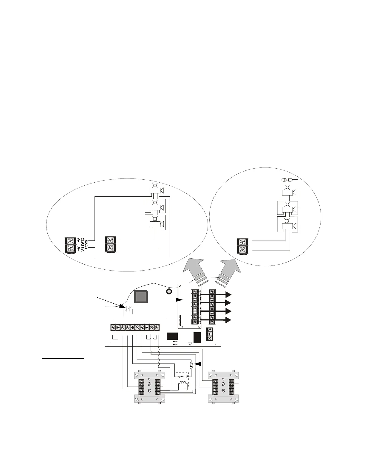
5.1 Controlling Four NACs With One Input and Selective Silence
In this application, the power supply has been set as a master with synchronized outputs
and selective silence (see SW1 switch settings in following illustration). All four
FCPS-24FS output circuits, which are shown as NACs (Notification Appliance
Circuits), can be controlled from one input such as an addressable control module as
illustrated in Figure 5.1. The control module can be powered from the FCPS-24FS
auxiliary 24 VDC power output (TB4, Terminals 9 & 10) and supervised by an EOL
relay. An addressable relay module, programmed as an alarm output and a silenceable
point, can be used as a selective silence input.
The control module is shown to demonstrate the use of a remotely mounted device
associated with an addressable fire alarm control panel. The module could be replaced
with any circuit capable of polarity reversal, such as an FACP NAC.
TB4
JP3
J3
TB5
TB2
JP1
JP2
OUT 4
-NAC4+
OUT4
-NAC4+
OUT 3
-NAC3+
OUT2
-NAC2+
OUT1
-NAC1+
AUX -
IN2-
IN2+
OUT1-
OUT1+
IN1-
IN1+
SYNC IN -
SYNC IN +
AUX +
NO NC
AUX TBL
COM
1 2 3 4 5 6 7 8 9 10
8
7
6
5
4
3
2
1
8
7
TB2
3
2
1
+
-
+
-
+
-
OUT4
-NAC4+
8
7
TB2
+
+
-
-
+
-
+
-
+
-
+
-
8
9
8
8
9
9
10
11
12
13
14
150
0
1
1
2
2
3
3
4
4
5
5
6
6
7
7
0
1
2
3
4
7
6
5
TENS
ONE S
ADDRESSLOOP
8
9
8
8
9
9
10
11
12
13
14
150
0
1
1
2
2
3
3
4
4
5
5
6
6
7
7
0
1
2
3
4
7
6
5
TENS
ONE S
ADDRESS
LOOP
Figure 5.1 Controlling Four Outputs With One Input
Control Module Relay Module
EOL Power
Supervision Relay
A77-716B
(energized)
SLCSLC
Style Z (Class A)
Style Y (Class B)
Use listed ELR (4.7KΩ)
to terminate Style Y
(Class B) NAC
Note: All NACs are supervised and power-limited
ZNAC-4
Option Module
Output/NAC 4
Output/NAC 3
Output/NAC 2
Output/NAC 1
FCPS-24FS has been set for
Selective Silence and Relay
Module has been programmed at
FACP as a silenceable point so it
can perform selective silence when
its Normally Open contact (7 & 9)
closes in alarm, then opens when
silence is invoked at the FACP.
Note: the Relay Module can be
mounted on the power supply
inside the cabinet. This allows
power wiring to remain inside the
cabinet.
SW1 Switch Settings
1 & 2 = sync (any setting but OFF/OFF)
3 = OFF (master)
4 = OFF (no AC Fail reporting delay)
5 = ON
6 = ON
7 = OFF (charger enabled)
8 = OFF (circuit 4 NAC function)
(selective silence)
End-of-Line Resistor
supplied with
Control Module
Internal Trouble Contact
ELR not required for
Style Z (Class A) NAC
FCPS-24FS
Horn/Strobes
Alarm Polarity Shown
Horn/Strobes
Alarm Polarity Shown
24fsapp7.cdr