MP-12/24 Fire Alarm Control Panel Document 15440:G 6/6/96
11
Power Limiting Notes Continued
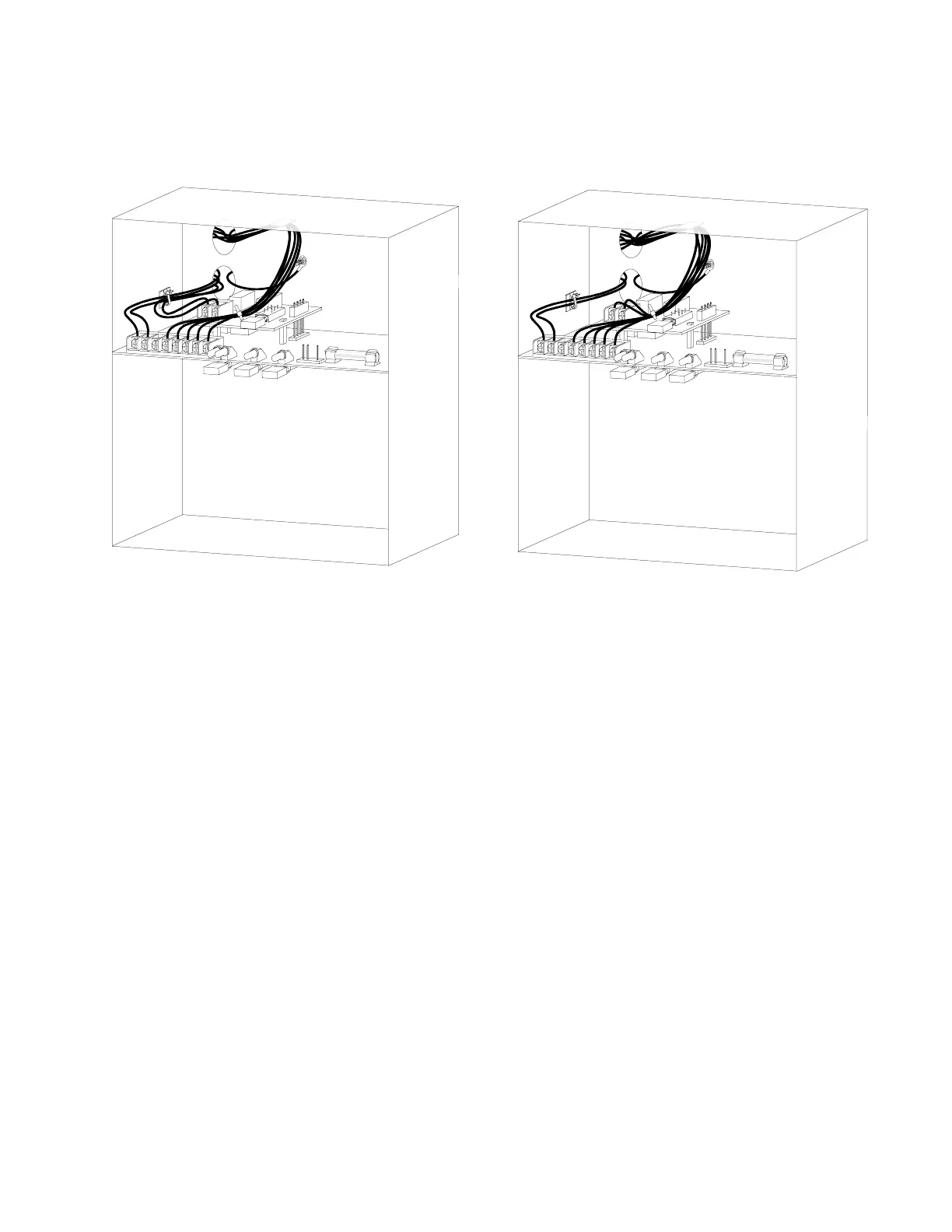
• For back knockouts, place the wire ties as shown in Figure 4.5.
• Use a lower knockout to run the wiring for non-power limited circuits and the upper knockout for
power limited circuits.
Alarm Initiating Devices
Wire all alarm initiating devices, including manual stations, heat detectors and smoke detectors, to zone
input terminals as shown in Figure 4.3. Refer to device data sheet for device connection information. Ob-
serve polarity when connecting polarized devices. Zone input terminals and polarity are:
Zone 1 Input: Terminal 7 positive, Terminal 6 negative.
Zone 2 Input: Terminal 7 positive, Terminal 8 negative.
All initiating devices connected to a given zone must be wired sequentially for proper supervision. Connect
the first device to the control panel, the second device connects to the first device, the third to the second
and so on. Remove the End-of-Line Resistor (ELR) from the control panel and install on terminals of the last
initiating device.
• Four-Wire Smoke Detectors
Power for four-wire smoke detectors may be obtained from terminals 5 (negative) and 7 (positive).
Supervise detector power with a listed end-of-line relay. Maximum current from terminals 5 and 7
should not exceed 100 mA. Two-wire detectors are recommended.
• Two-Wire Smoke Detectors
Compatible two-wire detectors can be connected directly to the zone input terminals. Polarity must
be observed. Two-wire detectors receive operating power from the zone terminals. Detector power
and alarm signals are transmitted through the same wires. The total peak standby detector current
per zone cannot exceed 2 mA. Compatible detectors are listed in the Device Compatibility Docu-
ment.
• Sprinkler System Waterflow Alarm Devices
Normally open waterflow alarm devices may be connected to this panel provided the system is used
in conjunction with a mechanical water motor gong.
Module shown connected to
power-limited circuit.
Module shown connected to
non power-limited circuit.
Figure 4.5: Typical wiring diagram for back knockouts