D4138
Fig. 1
5
39
1
4
6
2
7
8
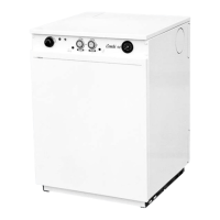
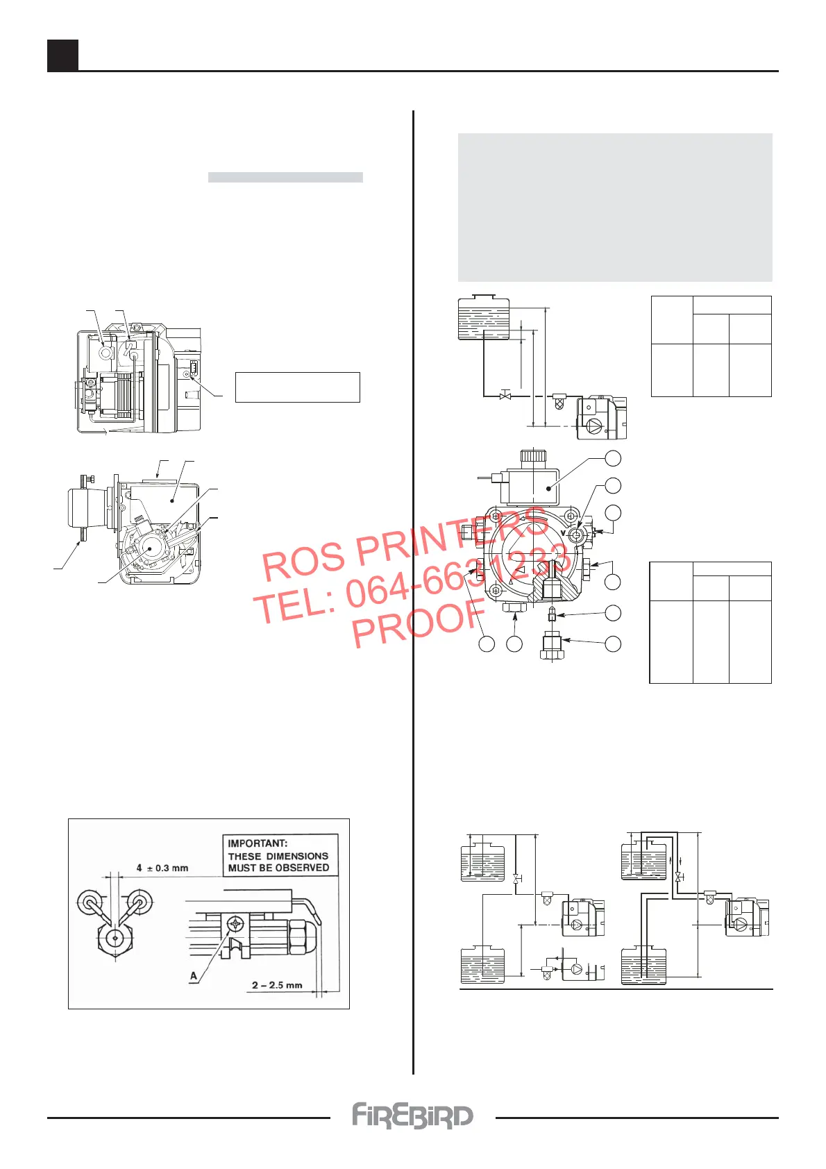
Burner Description
1 - Pump
2 - Control box
3 - RESET BUTTON WITH
LOCK-OUT LAMP
4 - Flange with insulating
gasket
5 - Air damper adjustment
screw
6 - Snorkel (BF)
7 - Pump pressure
adjustment screw
8 - Pressure gauge port
9 - Photoresistance
1.1 BURNER EQUIPMENT
Flange with insulating gasket . . . . . . . . N.º 1
Screw and nuts for flange . . . . . . . . . . . N.º 1
Hexagonal key . . . . . . .. . . . . . . . . . . . . N.º 1
Plastic air cover . . . . . . . . . . . . . . . . . . . N.º 1
Screws for flange to be fixed to boiler . . N.º 4
Flexible oil pipes with nipples . . . . . . .. . N.º 2
By-pass screw for 2 pipe system . . . . . .
N.º 1
One stage kerosene burner.
The intake air temperature must not be over 70 °C.
Burner with CE marking in conformity with EEC directives:
EMC 89/336/CEE and Efficiency 92/42/EEC.
CE Certification No.: 0036 0316/01 as 92/42/CEE.
ELECTRODE SETTING
Riello RDB 2.2
ATTENTION
Before assembling or removing the nozzle
loosen screw (A) and move electrodes forward.
F i g . 4
D5912
2
3
4
7
6
5
18
H
meters
L meters
I. D.
8 mm
I. D.
10 mm
0.5
1
1.5
2
10
20
40
60
20
40
80
100
H
meters
L meters
I. D.
8 mm
I. D.
10 mm
0
0.5
1
1.5
2
3
3.5
35
30
25
20
15
8
6
100
100
100
90
70
30
20
F i g . 6
F i g . 7
H
max. 4 m
min. 0.1 m
F i g . 5
D
5741
D5740
max. 4 m
H
H
max. 4 m
H
H
D1842
WARNING
• SINGLE PIPE
The pump is designed to allow working with one pipe.
• TWO PIPE
In order to obtain two pipe working it is necessary to unscrew the
return plug (2), screw in the by-pass screw (3) and then screw in
return oil line (2). (See fig. 4).
In the two pipe systems, before starting the burner make sure that
the return pipe-line is not clogged. An excessive back pressure
would cause the damage of the pump seal.
HYDRAULIC SYSTEM
1 - Suction pipe
2 - Return line
3 - By-pass screw
(* is supplied loose in burner pack )
4 - Pressure gauge connection
& Bleed screw
5 - Pressure adjuster
6 - Vacuum gauge connection
7 - Valve
8 - Auxiliary pressure test point
H = difference of level L = Max. length of the suction line
I.D. = Interminal diameter of the oil pipes
PRIMING PUMP:
On the system in fig. 5 it is sufficient to loosen the suction gauge
connection (6, fig. 4) and wait until oil flows out.
On the systems in fig. 6 and 7 start the burner an d wait for the prim in g.
Should lock-out occur pr ior to the arrival of the fuel, await at least 20
secon ds befor e r epeatin g the oper ation . The pum p suction should n ot
exceed a maxim um of 0,4 bar (30 cm Hg). Beyond this limit gas is r eleased
fr om the oil. Oil pipes must be completely tight.
I
n the vacuum systems (fig. 7) the r eturn line should terminate within the
oil tank at the same level as the suction line. In this case a non-return valve
is not required. Should however the return line arrive over the fuel level, a
n o n - r eturn valve is r equir ed. This solution however is less safe than
pr evious one, due to the possibility of leakage of the valve.
*