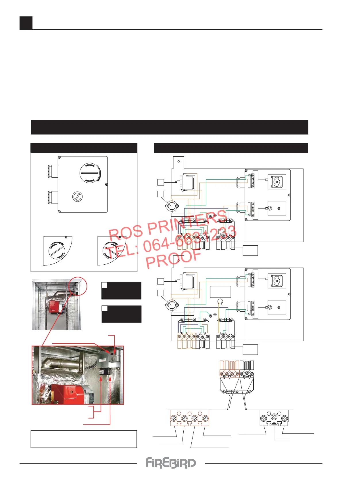
Use Heat Resistant Cable.
Protect Supply with 5 Amp. Fuse.
Firebird Systempac C Wiring Diagram
Pump
Connection.
Mains
Connection.
(B4) NEUTRAL
(S3) EARTH.
TIMED
SWITCH LIVE (T2)
PERMANENT
LIVE (T1)
B4
T1
T2
S3
N
L1
NEUTRAL (N)
EARTH.
PUMP LIVE (L1)
B4
N
T1
T2
S3
L1
Temperature
Control Dial.
Max 80˚C.
Min 60˚C.
Firebird I. Dual Thermostat
Temperature Control.
Min 60˚C.
MIN. MAX.
Max 80˚C.
MIN.
MAX.
MIN. MAX.
High Limit
Thermostat.
Reset Pin Inside
Screw Off Cover.
Control
Thermostat.
Te mperature Control
High Limit re-set button
7 Pin Plug
Burner Plug
Power Supply & Pump
Power To
Burner
Safety Limit
Thermostat.
B4
N
T1
T2 B3
L1
N
L1
L2
Blue
Brown
Control Thermostat.
E
E
L
N
X
L
N
X
2
C
1
A
B
Power To
Burner
Safety Limit
Thermostat.
B4
N
T1
T2 B3
L1
N
L1
L2
Blue
Brown
Control Thermostat.
E
E
L
N
X
L
N
X
2
C
1
A
B
Pressure
Switch
Enviromax 7 Pin Plug Systempac Wiring
Pump Over
Run Thermostat
87˚C.
A
Bi. Metal
Frost Thermostat.
5˚C. / 14˚C.
B
ELECTRICAL SUPPLY
The boiler and controls require 230V 1 phase 50Hz mains electric supply protected with a 5amp fuse.
The guarantee on this product will be rendered void if damaged by power from a stand by electricity supply. i.e. (Generator.)
A qualified electrician must carry out all electric wiring in accordance with current I.E.E Regulations and any local regulations
which may apply.
The mains electrical supply must be taken from a double pole isolating switch with a 5amp fuse, positioned somewhere close
to the boiler. Heat resisting cable must be used which can be routed into the boiler through the access provided on either
side of the base. Ancillary controls may be provided for with terminal connections in the control panel.