FirePro
138 – 140 Bayeld Rd East,
Bayswater North, VIC, 3153.
Australia.
P (03) 9720 4333
F (03) 9720 4344
MODEL NUMBER: FP510V
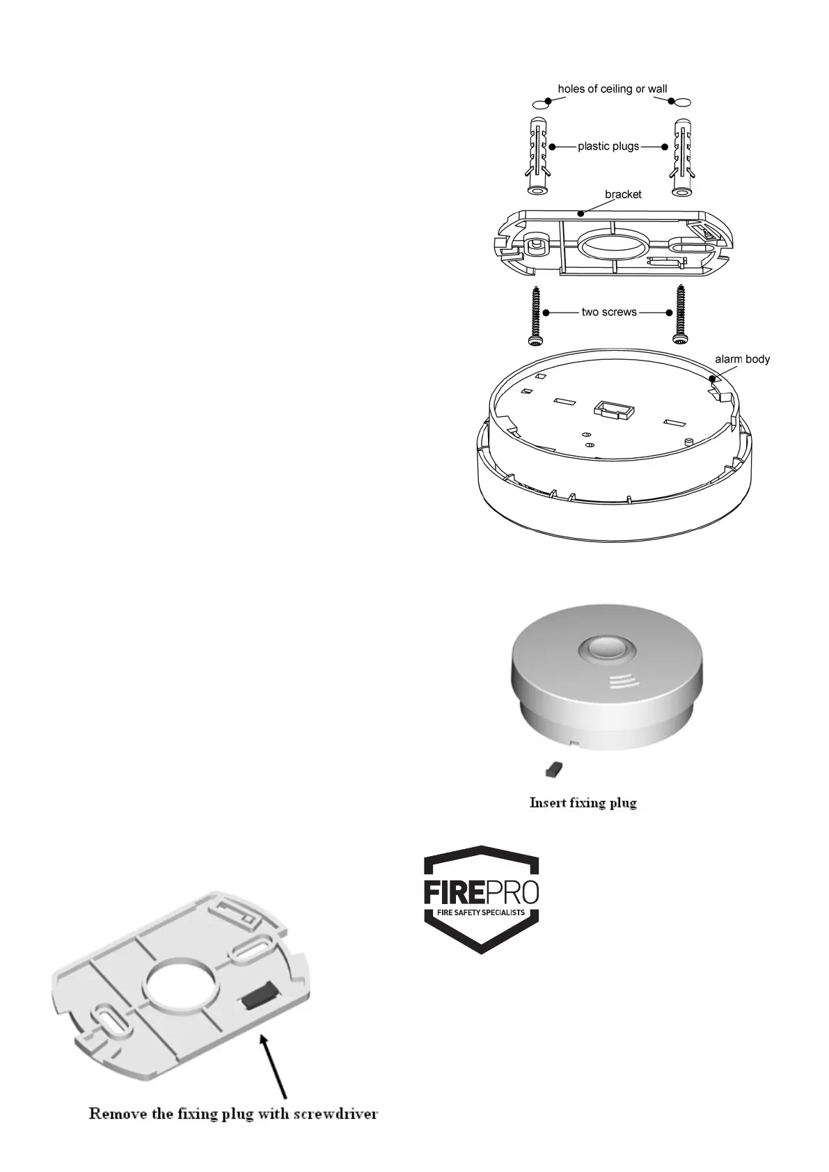
Diagram 8
- 6 -
Installation:
Activation
Press test button and hold it for about 3 seconds until
LED lights, and release it within 2 seconds, the unit will
generate a “beep” indicating that it is activated and is in
working status
CAUTION: You MUST activate alarm rst, or else there is
no function for this unit.
• Turn the alarm body counterclockwise and take off the
bracket.
• Place the bracket in the installation position, mark
installation hole of the bracket with pencil.
• Drill two installation holes with electric drill. Make diameter
of holes 5mm, Strike the two plastic plugs into holes with
hammer.
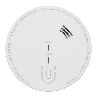
• Remove xing plug from the bracket with screwdriver if
necessary (See Diagram 7).
• Attach the bracket to the plastic plugs and x the screws
tightly into the plastic plugs (See Diagram 8).
• Fit the alarm on the bracket and turn the alarm body
clockwise, until matching well on the bracket.
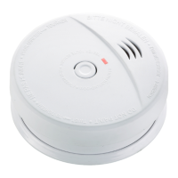
• Insert xing plug to the gap between bracket and bottom
cover for xing alarm if you want (See Diagram 9).
• Press the button to test the unit. The alarm sounds 3 beeps –
1.5 seconds pause, repeat it until release the button. If there
is no sound, it indicates a defective alarm, you can refer to
”Trouble shooting” for solution or return to your retailer
during warranty.
• If you have any questions on installation, you can contact
your retailer.
WARNING:
To prevent injury, this unit must be securely attached to the
wall or ceiling in accordance with the installation instructions.
Diagram 7
Diagram 9