Page 4
Wiring
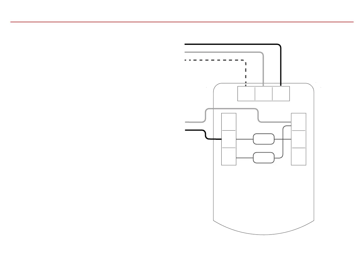
The Fireray One contains software that
processes the output of the detector and
generates a Fire and Fault status. This status
is output using volt-free relays so that it can
be interfaced to all types of conventional Fire
Control Panel (FCP). To wire a single Detector
to an FCP, use the following wiring diagram.
Components not supplied:
1. Fire Resistor (Note 1) - value is specified by
the FCP manufacturer.
For U.S. installations it is typically a short
circuit.
2. End Of Line (‘EOL’) component - supplied
by FCP manufacturer
After installation, check operation of Fire and
Fault connections to the FCP - see page 15.
Apply a voltage of 5V to 40V to ‘Ext Reset’
contact for at least 2 seconds to clear a latched
fire condition – see page 14 for latching mode
setting.
CAUTION: For system monitoring – Do not
use looped wire under any terminals.
Breakwire run to provide monitoring of con-
nections.
Note 1
EOL
N/O
COM
N/C
N/O
COM
N/C
Ext
Reset
-
+
Supply +
Supply -
Ext Reset
Zone -
Zone +
Fault
Fire