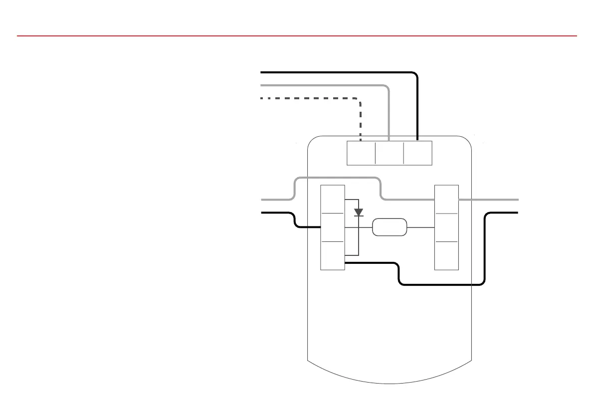
EasyManuals Logo

Fireray One User Manual

Fireray One
84 pages
To Next Page IconTo Next Page
To Previous Page IconTo Previous Page
Page #7 background imageLoading...
Page #7 background image
Page 5
Supply +
Supply -
Ext Reset
Zone - In
Zone +In
Note 1
Zone - Out
Zone + Out
Fault Fire
N/O
COM
N/C
N/O
COM
N/C
-
+
When using more than one Detector on a
single zone of a conventional FCP, it is
important to choose the correct method
of wiring. Incorrect wiring may result in a
Detector isolating subsequent devices on that
zone if it enters a Fault condition, and may
prevent these subsequent devices signalling a
Fire condition back to the FCP.
If the FCP monitors for point detector
removal, it is possible to use the following
wiring diagram which uses a diode to provide
zone continuity in the event of a Fault state on
any Detector.
Recommended diode type: Schottky, 60 Volt,
1 Amp, must be UL listed for installations
meeting NFPA72
Ext
Reset

Questions and Answers:

Question and Answer IconNeed help?

Do you have a question about the Fireray One and is the answer not in the manual?

Fireray One Specifications

General IconGeneral
IP RatingIP65
Detection MethodInfrared Beam
Detection RangeUp to 200m
RangeUp to 200m
Operating Voltage12-24V DC
Voltage Range12-24V DC
Power Supply12-24V DC
Alarm Relay1A @ 30V DC
Fault Relay1A @ 30V DC
OutputRelay
Operating Temperature+55°C
Temperature Range+55°C
HousingPolycarbonate
TypeInfrared Beam Detector