Do you have a question about the Fireye MicroM MEC120 and is the answer not in the manual?
General procedures for installing MicroM controls, scanners, and flame detectors.
Steps for inserting programmer and amplifier modules into the MicroM chassis.
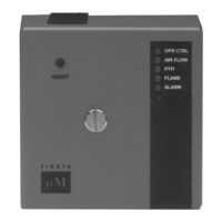
Lists lockout codes and their corresponding LED status indicators for troubleshooting.
Lists possible causes and solutions for diagnostic messages in the MicroM system.
Procedures for performing tests during installation to verify system functionality.
Details how to use a multimeter for testing MicroM controls and flame signals.
Procedure for testing pilot flame with Run/Check switch for programmers.
Procedure to ensure flame detector does not sense a pilot flame too small to light main.
Procedure to test flame failure detection and UV detector response to ignition spark.
Flowchart for diagnosing and resolving normal lockout conditions in MicroM systems.
Flowcharts for diagnosing issues in Situations #2, #3, and #4.
Diagrams illustrating standard wiring for various burner types and programmers.
Diagram for wiring pilot ignited burners with MEP100 and MEP200 series programmers.
Diagram for wiring pilot ignited burners with main flame stabilization using MEP236.
Diagram for direct spark ignited burners with two-stage operation using MEP100/MEP200.
Diagram for pilot ignited burners with interrupted pilot using MEP500 series programmers.
Diagram for direct spark ignited burners with interrupted ignition using MEP500.
Diagram for configuring MEP100 programmers for flame switch operation.
| Brand | Fireye |
|---|---|
| Model | MicroM MEC120 |
| Category | Control Unit |
| Language | English |