EasyManua.ls Logo

Fireye MicroM Series - User Manual

Fireye MicroM Series
58 pages
Print Icon
To Next Page IconTo Next Page
Loading...
1
FIREYE
MODULAR
MicroM
FLAME SAFEGUARD CONTROLS
WARNING: Selection of this control for a particular application should be made by a com-
petent professional, licensed by a state or other government agency. Inappropriate application
of this product could result in an unsafe condition hazardous to life and property.
DESCRIPTION
The Fireye MicroM Series Flame Safeguard Control is a compact, microprocessor based, modular
burner management system designed to provide automatic ignition and continuous flame monitoring
for commercial sizes of heating and process equipment firing any type of fuel.
The MicroM is designed to be backward compatible with existing TFM, UVM and M-Series II con-
trols. The MicroM MEC120 and MEC230 chassis with the appropriate MEP100, MEP200 and
MEP500 series programmers provide operation similar to its predecessors and is usually directly
interchangeable. The MEC320 and MEC480 chassis with the appropriate MEP300, MEP400 and
MEP600 series programmers provide additional enhancements such as early spark termination, pilot
proving, and interrupted pilot.
The advantages of the MicroM are zero dependence on discrete components previously used for tim-
ing functions. The MicroM, through the use of micro-controller technology, incorporates smart diag-
nostic LED's, smart reset function for multi-burner applications, optional alpha-numeric display
output (ED510), and serial communications via a Modbus or E500 Communication Interface. The
MicroM system also provides additional amplifier selections. Along with the standard UV and
Flame Rod amplifiers are UV self-check, Infrared, Cadmium Sulfide and a dry contact amplifier for
use with the Fireye Phoenix scanner. All amplifiers are available with flame failure response times of
0.8 seconds or 3 seconds nominal (4 second maximum) and each provide a set of test jacks with a
uniform range of 0-10 VDC for the measurement of flame signal intensity.
A complete MicroM system includes the appropriate flame detector, plug-in amplifier and program-
mer modules which connect into a standard chassis and wiring base. Interchangeable programmer
and amplifier modules allow for complete versatility in selection of control function, timing and
flame scanning means. Functions such as relight, recycle, non-recycle, two stage capability, non-
recycle air flow, proof of air flow open at start, purge timing, early spark termination, pilot proving
and pilot cutoff are determined by the appropriate programmer module. Type of flame scanner (UV,
Repetitive UV Self-Check, Flame Rod, IR or Cadmium Sulfide or dry contact) and the flame failure
response time (FFRT) are determined by the amplifier module. Optional plug-in daughter boards
provide additional features such as remote reset, alpha-numeric display and serial communications.
The MicroM programmers are micro-controller based modules that control the sequence of opera-
tion and also interface with plug-in amplifiers, meter boards, display drivers and external communi-
cation devices. The programmers are available in an assortment of configurations necessary to
resolve the application requirement. Current families of programmers for use with the MEC120 and
MC-5000
MAY 10, 2017
APPROVED

Table of Contents

Question and Answer IconNeed help?

Do you have a question about the Fireye MicroM Series and is the answer not in the manual?

Fireye MicroM Series Specifications

General IconGeneral
BrandFireye
ModelMicroM Series
CategoryControl Unit
LanguageEnglish

Summary

Product Description

Specifications

Ambient Temperature Limits

Specifies operational temperature range for various controls and scanners.

Approvals

Ordering Information

MicroM Chassis and Programmer Models

Lists available chassis and programmer models for different applications and voltage inputs.

MicroM Amplifier Models

Details various amplifier types, their FFRT, and compatible scanners for flame detection.

Optional Plug-In Boards

Plug-In Board Location and Installation

Instructions for installing optional boards like remote reset, display, or communication modules.

Installation of Control, Scanners and Flame Detectors

Wiring Base Installation

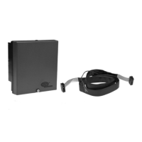
Guidelines for mounting the wiring base, ensuring proper grounding and wiring practices.

Installing Programmer and Amplifier Modules

Replaceable Fuse

Location and procedure for replacing the field-replaceable fuse in the chassis.

Programmer Dipswitch Settings

Dipswitch Configuration and Definitions

Explains dipswitch functions for programming purge, PTFI, and recycle modes.

LED Indicator Lights

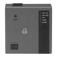
Describes the function of the 5 LEDs for status indication and lockout codes.

Lockout Codes

Diagnostic Messages - Troubleshooting Guide

Troubleshooting Flowcharts

Visual guides for diagnosing normal lockout and specific system situations.

Programmer Descriptions

MEP100 Series Programmer Description

Details operation, safety shutdown, and specific functions of MEP100 models.

MEP200 Series Programmer Description

MEP500 Series Programmer Description

MEP300;MEP600 Series Programmer Description

Remote Reset Functionality

Remote Display

ED510 Display Operation and Data

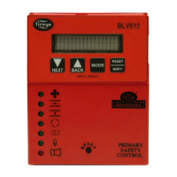
How to navigate the ED510 display for status, history, and configuration.

Communications

Communication Parameters and Addressing

Details Modbus RTU protocol, baud rates, data formats, and unit addressing.

Installation Testing Procedures

Pilot Flame Testing Procedures

Methods for testing pilot flame, including minimum pilot and flame failure tests.

Wiring Arrangements

Pilot and Direct Spark Ignited Burner Wiring Diagrams

Standard wiring diagrams for pilot and direct spark ignited burners using MEP series.

Alternate and Backward Compatible Wiring Diagrams

Shows alternative and compatible wiring configurations for various MEP programmer series.

Suggested Grounding Rules

Scanners

Scanner Maintenance and Installation

Covers cleaning, maintenance, and installation procedures for UV, Infrared, and Flame Rod scanners.

Maintenance

Periodic Safety Check

Recommends monthly tests for all limit switches, interlocks, and flame failure protection.

Cross Reference Listing

Module Replacement Information

Provides cross-reference for M-Series II to MicroM modules and dipswitch settings.

Warranties

Related product manuals