Do you have a question about the Fireye YB110 and is the answer not in the manual?
Microprocessor-based burner management system for automatic oil, gas, and combination fuel burners.
Details the voltage requirements (120/230 VAC) and power consumption (25 VA) for the BurnerLogix system.
Specifies operating temperature limits and protection categories (NEMA 1, NEMA 4X) for the control and display modules.
Lists approvals from Underwriters Laboratories, Factory Mutual, CE, DVGW, and DIN-CERTCO.
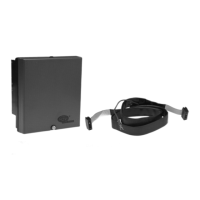
Lists chassis/amplifier modules, programmer modules, and display modules for ordering the BurnerLogix system.
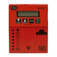
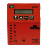
Provides visual identification and configuration details for chassis/amplifiers, programmer modules, display modules, and wiring bases.
Details the selection and mounting of pre-wired or terminal block wiring bases for the BurnerLogix system.
Lists terminal numbers, wire colors, types, descriptions, and ratings for the 120 VAC pre-wired wiring base.
Provides guidelines for wiring base installation, including humidity, vibration, NEC compliance, wire routing, and maximum wire lengths.
Describes how to properly install the YP programmer module into the YB chassis, emphasizing correct orientation.
Details electrical tests using an ohmmeter to check for short circuits and grounds before applying power.
Explains how programmers determine functional operation and lists factory default settings for various YP programmers.
Details selectable timings for PTFI and MTFI, including options for early spark termination and their effects.
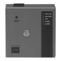
Explains the function of each of the seven LED indicator lights and their associated graphic symbols.
Details the location and replacement procedure for the field-replaceable fuse on YB110 controls.
Explains the role of operating controls, limit switches, fuel valve interlocks, purge interlocks, running interlocks, and low fire start interlocks.
Describes how to configure programmer parameters using the optional keypad/display and the PROGRAM SETUP sub-menu.
Explains the functions of the NEXT, BACK, MODE, and RESET/MDFY keys for navigating menus and modifying parameters.
Details how to access and modify operational settings like purge timing, flame fail time, and baud rate within the PROGRAM SETUP sub-menu.
Covers UV scanner application, installation, best practices, wiring, and operation, including self-checking types.
Details installation, wiring, operation, cooling, and maintenance for infrared scanners like the 48PT2 and 69ND1 flame rod.
Explains how to review system information, burner history, lockouts, and select language options via the SYSTEM INFO sub-menu.
Introduces the YP100 programmer functions and messages, referencing specific bulletins for detailed information.
Illustrates the sequence of operation for the YP100 programmer, showing terminal states during different cycle phases.
Details the step-by-step process of a normal burner start-up sequence, including purge and trial for ignition.
Shows the operating sequence for the YP200 programmer, outlining terminal states during various stages of the burner cycle.
Depicts the operating sequence for the YP300 programmer, detailing terminal status across different burner cycle phases.
Provides suggested wiring diagrams for YP100 and YP200 programmers, including terminal connections and typical arrangements.
Presents suggested wiring diagrams for YP300 programmers, detailing terminal usage and specific component connections.
Illustrates wiring diagrams for the YP138 programmer, highlighting its extended functions and additional input terminals.
Explains how safety shutdowns occur, the role of interlocks, and the conditions that lead to control lockout.
Details the process for proving the 3-P running interlock circuit closed and the resulting lockout causes.
Lists diagnostic messages, their possible causes, and suggested solutions for troubleshooting BurnerLogix system issues.
Describes the three methods for resetting the BurnerLogix system: push-button, keypad, and external switch.
Provides a table correlating lockout messages with illuminated LED indicators to identify the reason for a lockout.
Explains how to navigate the LOCKOUT HISTORY sub-menu to view the last ten lockouts, including cycle and hour data.
Details the Modbus RTU protocol used for communication, including message formats, register addresses, and data transmission.
Lists Modbus holding registers, their addresses, requested words, responses, and associated values for system data.
Explains the data format for inputs and outputs, including bit representation of interlocks and output relays.
Details the mapping of YZ300 interlock annunciator states (lockout, hold) to specific terminals and logic conditions.
Defines LOGSTAT as an indicator of the control's current operating logic module and lists its values and corresponding functions.
Lists BurnerLogix messages, their hex/decimal codes, state, terminal, and descriptions for diagnostic purposes.
Lists specific message codes related to purge interlock conditions, their states, and associated terminals.
Correlates YZ300 interlock annunciator codes with terminal states for lockout conditions.
Explains the use of 4-20 mA test jacks to monitor flame signal strength and their correlation to display readings.
Details how to use the Check-Run switch to stop the control in the sequence for setup, start-up, and check-out procedures.
Outlines safety precautions, manual shut-off valve procedures, and checks for limit circuits and automatic valves before testing.
Describes voltage checks on the L1-L2 supply and other terminals to identify potential power issues.
Details procedures for testing pilot flame failure response, main flame failure protection, and minimum pilot flame detection.
Advises on routing ignitor and scanner cables separately to prevent interference and ensure proper operation.
Provides rules for establishing an effective ground system for the microprocessor-based BurnerLogix system.
Explains routine cleaning procedures for scanner viewing areas and flame rods to ensure accurate detection.
Covers maintenance for remote displays, communication interfaces, and ensuring proper installation of related cables.
Advises periodic inspection of spark electrodes, ignition transformers, and wiring neatness for reliable operation.
| Brand | Fireye |
|---|---|
| Model | YB110 |
| Category | Control Unit |
| Language | English |