11
®
INSTALLATION PROCEDURE
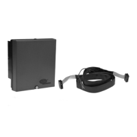
WIRING BASE
Select either the pre-wired wiring base (60-2810-1) or terminal block style (60-2812-1, 60-2814-1).
Either wiring base type can be mounted on a din rail or directly mounted to the cabinet back plate.
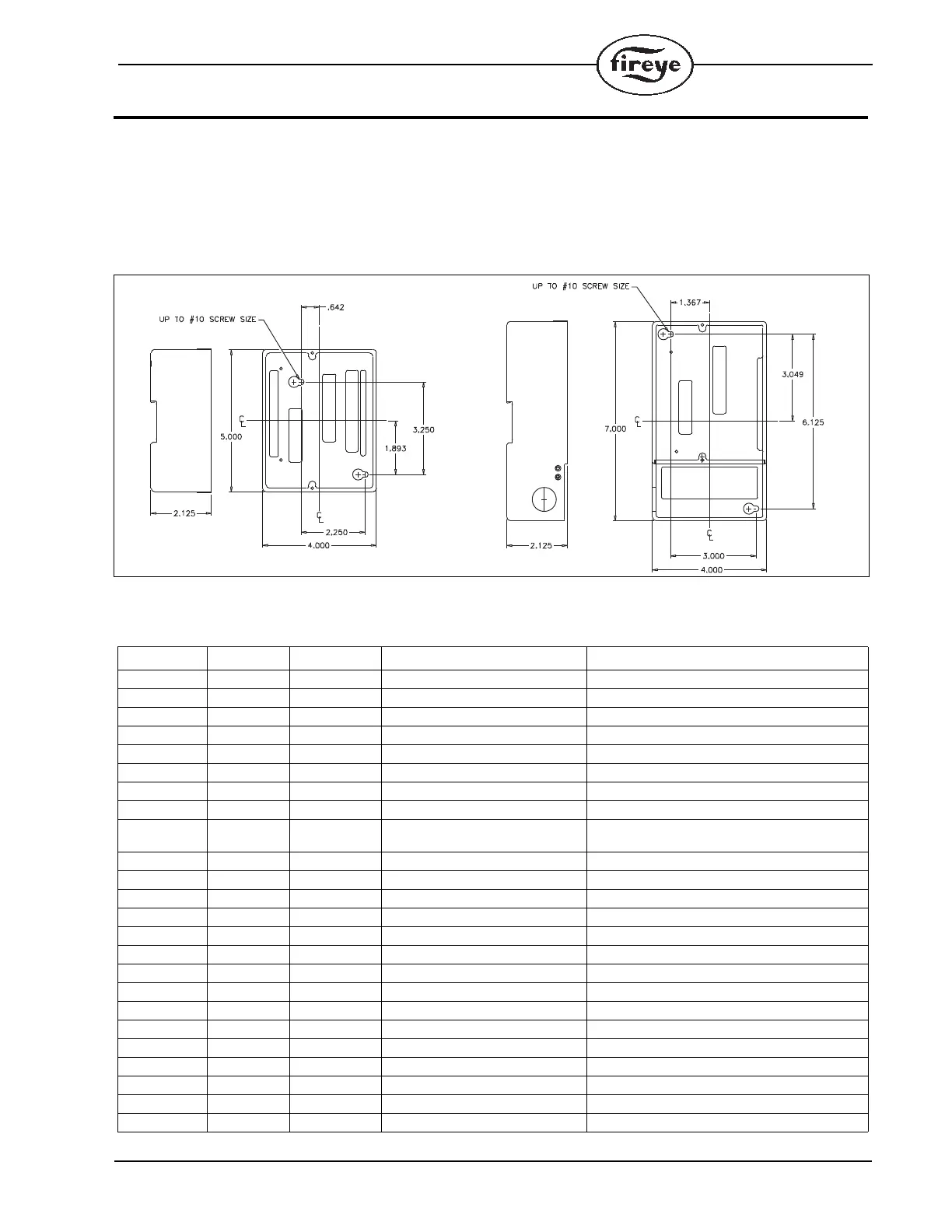
Refer to Figure 1 for mounting dimensions.
FIGURE 1.
The location should be free from excessive vibration and within the ambient temperature rating.
PRE-WIRED WIRING BASE, P/N 60-2810-1 (shown for 120 VAC)
Terminal No. Wire Color Type Description Rating
L1 (Hot) Black Line voltage supply 120 VAC (+10%,-15%), 50/60 Hz
L2 (Neutral) White Line voltage common
EARTH Green Ground
S1 Red/Wht Scanner Input 300 VAC, 3 mA (UV models only)
S2 Blu/Wht Scanner Input 300 VAC, 3 mA (UV models only)
A Red Output Alarm 120 VAC, 1 A pilot duty
M Brown Output Combustion Blower 120 VAC, 9.8 FLA, 58.8 LRA
3 Yellow Input Operating Control 120 VAC, 1 mA
13 Orange Input Fuel Valve End Switch,
Pre-Ignition Interlock
120 VAC, 1 mA
P Gray Input Running Interlock 120 VAC, 1 mA
D Wht/Brn Input Low Fire Start Switch 120 VAC, 1 mA
8 Wht/Gry Input Open Damper Proving Switch 120 VAC, 1 mA
W Wht/Orn Output Delayed Main Valve See Load Ratings
5 LT Blue Output Ignition / Pilot Valve See Load Ratings
6 Tan Output Pilot Valve See Load Ratings
7 Violet Output Main Fuel Valve See Load Ratings
16 DK Blue Input Pilot Valve Hold 120 VAC, 1 mA
21 Pink Input Start Input 120 VAC, 1 mA
10 Wht/Red Output Modulator Common 120 VAC 75 VA
12 Wht/Yel Output Modulator Low Fire 120 VAC 75 VA
X Wht/Blue Output Modulator High Fire 120 VAC 75 VA
11 Wht/Grn Output Modulator Auto 120 VAC 75 VA
22 Wht/Vio Input Remote Reset 120 VAC, 1 mA
23 Brn/Wht Input Spare 2 120 VAC, 1 mA
HEIGHT WITH CONTROL INSTALLED IS 5.8" (147MM)
 Loading...