48
than halfway through. Swivel flanges are available if desired (#60-302 for UV1A, UV2 Scan-
ners, #60-1664-3 for 45UV5). The sight pipe must permit an unobstructed view of the pilot and/
or main flame, and both pilot and main flames must completely cover the scanner field of view.
5. Smoke or unburned combustion gases absorb ultraviolet energy. On installations with negative
pressure combustion chambers, a small hole drilled in the UV1A, UV2 sight pipe will assist in
keeping the pipe clean and free from smoke. For positive pressure furnaces, provide clean air to
pressurize the sight pipe, if necessary.
6. Two UV1A or UV2 Scanners may be installed on the burner if it is necessary to view two areas
to obtain reliable detection of the flame. They should be wired in parallel. Only one repetitive
self- checking 45UV5 Scanner may be installed on a burner.
To increase scanner sensitivity with UV1A, UV2 Scanners, a quartz lens permits location of the
scanner at twice the normal distance. Use 1/2" x 1 1/2" pipe nipple between UV1A Scanner and the
coupling. Use 3/8" pipe nipple and a 1/2" x 3/8" bushing on UV2 installations.
7. Request the assistance of any Fireye field office for recommendations of a proper scanner instal-
lation on a non-standard application.
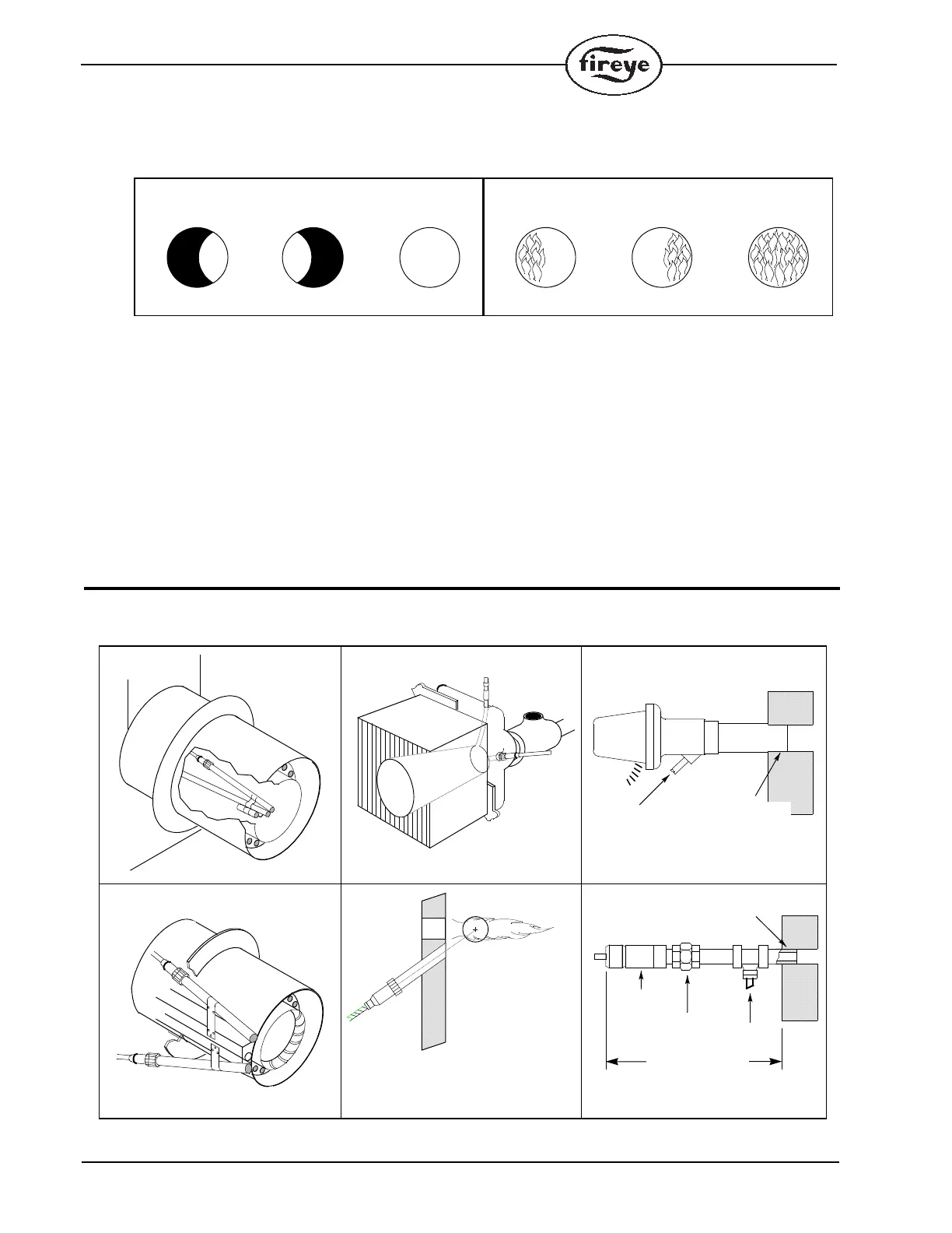
TYPICAL SCANNER INSTALLATIONS
SCANNER MUST HAVE UNOBSTRUCTED
VIEW OF FLAME
NOT THIS NOT THIS BUT THIS
FLAME MUST COMPLETELY COVER
SIGHT OPENING
NOT THIS
NOT THIS BUT THIS
The maximum UV signal
from a flame is found in
the first one-third of the
visible flame taken from
the point where the flame
begins. The scanner sight
pipe should be aimed at
this area.
DO NOT EXTEND
MORE THAN
HALF-WAY INTO
REFRACTORY
SCANNER
FORCED
CLEAN AIR
(FROM DISCHARGE
OF FAN)
METHODS OF COOLING SCANNER
INSULATING
TUBING
SEALING
UNION
FORCED
AIR
EXTEND SIGHTING TUBE
6”(152.4) OR 8”(203.2)
DO NOT EXTEND MORE THAN
HALF-WAY INTO REFRACTORY
 Loading...