14
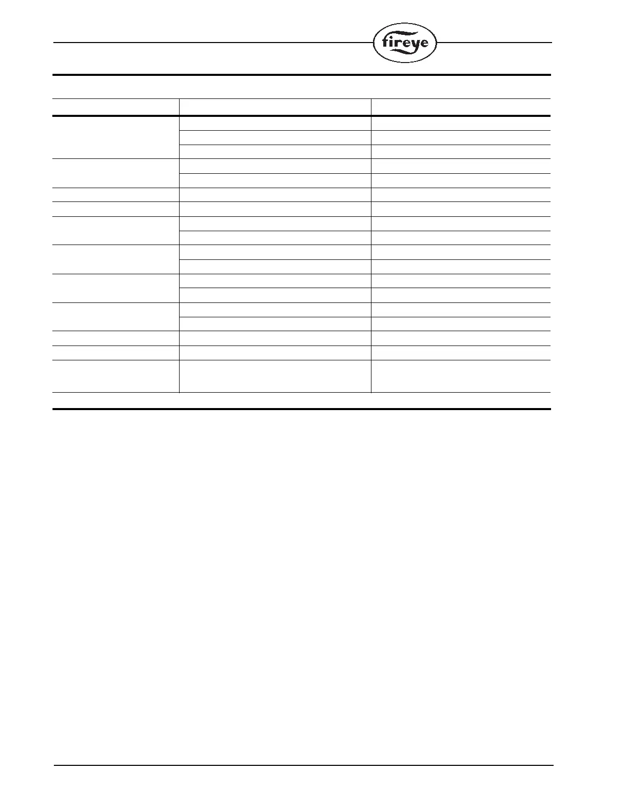
DIAGNOSTIC MESSAGES - TROUBLESHOOTING GUIDE
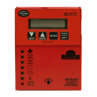
PROGRAMMER DESCRIPTION
For replacement of UVM, TFM and M-II type controls, refer to the cross-reference provided at the end of
this section.
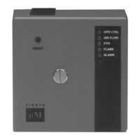
MEP100 SERIES
MEP100 and MEP101
These programmers provide relight operation, in the event of a flame failure, pilot trial for ignition is
reinitiated. The MEP101 will not lock out if flame signal is present during the Idle or Off cycle. With
flame signal present, lockout will occur 60 seconds after the start of a cycle and the air flow switch is
closed.
Pilot Ignited Burners
Refer to typical wiring arrangement beginning on page 38.
Normal Operation
With power applied and the limit operating control circuit (1-7) closed, the Operating Control LED
illuminates, the burner motor circuit is energized (Terminal 8).
After the air flow proving switch (7-6) closes, the interlock (air flow) LED is illuminated and a short
time delay period (3-5 seconds) begins.
At the expiration of the safe start check period, a 10 second pilot trial for ignition (PTFI) period is
initiated, illuminating the PTFI Led. Power is applied to Terminal 3, energizing the pilot gas valve
and to Terminal 4, energizing the spark ignition.
At the detection of pilot flame, the FLAME LED is illuminated, and the programmer holds that posi-
tion for 3 seconds to allow the to pilot stabilize.
Power is then applied to Terminal 5 energizing the main fuel valve and removing power from Termi-
nal 4, turning off the spark igniter.
When the operating control opens, the control de-energizes Terminal 3 and Terminal 5 and the pro-
grammer reverts back to an Idle state.
POSSIBLE CAUSE SOLUTION
Check Programmer Voltage on Terminal 5 at improper time. Inspect wiring to main fuel valve
Welded watchdog relay Replace MEC chassis
Internal diagnostic failure Replace MEP programmer
Check Chassis Voltage on Terminal 3 or 4 at improper time. Inspect wiring to pilot valve and igniter.
Welded watchdog relay Replace MEC chassis
Chassis Opto Opto-Coupler(s) short circuited Replace MEC chassis
Amplifier High Count Fail Amplifier signal level high Replace Amplifier module
Amplifier Auto Check Fail Flame signal too high Use orifice in sight pipe
Internal Amplifier diagnostic fault Replace Amplifier module
Check Scanner Defective shutter Inspect scanner wiring, replace scanner
UV tube false firing Replace UV tube or scanner
Check Blown Fuse No power detected on terminal 3 Inspect defective pilot valve or igniter
Defective fuse Replace fuse
Line Frequency Noise Detected Spikes detected on AC mains Check for SCR motors or DC drives
Inspect ground system
Fuel Value State Change Terminal 5 (main fuel) detected on during PTFI Check external wiring or replace MEC chassis
Check Amplifier Amplifier not passing diagnostic tests Replace Amplifier module
System Error Noise transient Check high energy ignition noise location. Be
sure it is not arcing to chassis or wrapped
with scanner wiring.
 Loading...