10
INSTALLING THE PROGRAMMER AND AMPLIFIER MODULES
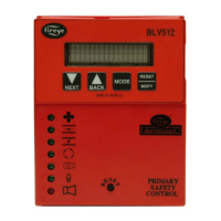
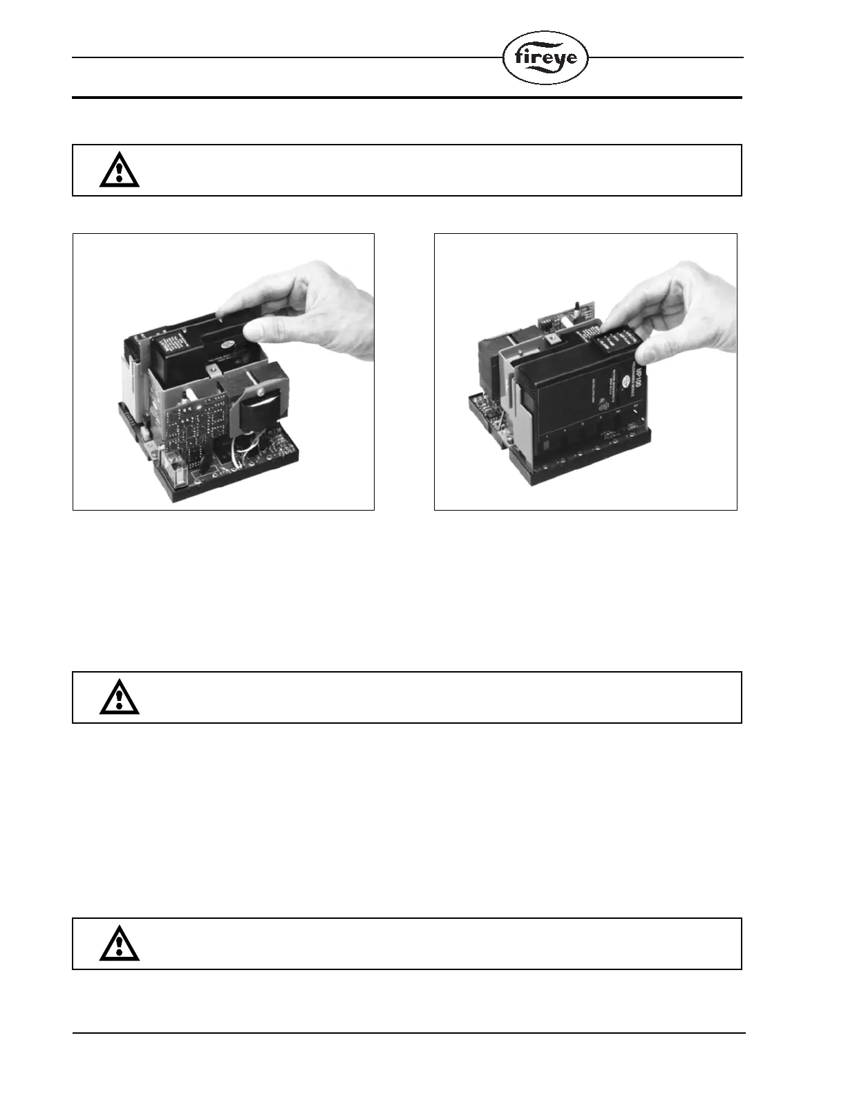
FIGURE 1. .
Select the appropriate programmer and amplifier modules for your application. Remove the dust
cover from the chassis. Insert the amplifier module into the slot in the corner of the chassis and gen-
tly push the module into position. Insert the programmer module into the slot at the right side of the
chassis and gently push the module into position.
NOTE: Refer to programmer dipswitch settings on page 11 for the proper setting of the dipswitches
for those programmers with this feature.
Replaceable Fuse
The chassis modules are designed with a field replaceable fuse. The fuse is located on the printed cir-
cuit board below the transformer. In the event the fuse becomes OPEN, the Operating Control, PTFI,
and Flame LED’s will light. However, KL or KF (Wiring Arrangements section on pages 33 through
38) will not be energized and the control will lock out and indicate Lockout, Check Blown Fuse. The
fuse will blow as a result of an overload condition on Terminals 3, 4, or 5. To replace the fuse,
remove power from the system and using a small screwdriver or similar tool, install a Fireye replace-
ment fuse (P/N 23-197).
FOR MEC230, ORDER FIREYE REPLACEMENT FUSE P/N 23-198 .
WARNING: Remove power from the control before proceeding.
WARNING: Turn off the power when installing or removing the control.
WARNING: Disconnect power before servicing.
 Loading...