13
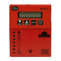
PTFI: This LED is illuminated only during the pilot trial for ignition period and the stabilization
period when so equipped.
Flame: This LED is on whenever a flame signal is detected, and the control is not in a locked out
state.
Alarm: This LED flashes when an alarm condition is detected and is used as an address indicator
(see communication).
During an alarm condition, the Alarm LED is made to flash at approximately a 1 second rate. The
remaining four LEDs are illuminated as a coded sequence identifying the reason for the lockout. For
instance, for a LOCKOUT - FLAME FAIL- PTFI, the INTERLOCK, PTFI and FLAME LED’s will
all be lit steady, with the Alarm LED flashing. This remains true if power is removed and then
restored in a locked out condition.
While in the Idle or Off state, the LEDs are made to flash sequentially to show the operational status
of the control every minute. The LEDs can be tested by pressing and releasing the Reset push button,
while in the Idle or Off state.
LOCKOUT CODES
All LED’s Flashing indicates defective programmer.
All MicroM chassis are shipped with a convenient peel off label that can be applied to any
surface (inside cover) for future reference.
MSGN DESCRIPTION OP
CTRL
AIRFLOW
INTLCK
PTFI FLAME ALARM
DEC HEX
6 6 Lockout Line Frequency Noise Detected
7 7 Lockout Flame Fail - PTFI
15 0F Lockout Fault Unknown
16 10 Lockout Amplifier High Count Fail
19 13 Lockout Flame Fail - MTFI
20 14 Lockout False Flame - STANDBY
21 15 Lockout Intrlck Open
22 16 Lockout Intrlck Closed
24 18 Lockout Chassis Opto
37 25 Lockout Flame Fail - AUTO
39 27 Lockout Fuel Valve State Change
54 36 Lockout Check Chassis
55 37 Lockout Check Programmer
56 38 Lockout Check Amplifier
58 3A Lockout Amplifier Auto Check Fail
59 3B Lockout Check BLOWN FUSE
76 4C Lockout Check Scanner
N/A N/A System Error
= NOT LIGHTED
= LIGHTED
= FLASHING
 Loading...